
Theory
Introduction
Read-Only Memory (ROM) is a vital component of digital systems and computer architecture, specifically designed for permanent data storage. Unlike RAM (Random Access Memory), which is volatile and loses data when power is turned off, ROM retains its contents indefinitely, even without a power supply. This non-volatile nature makes ROM an essential element in systems requiring fixed instructions or data, such as firmware, system initialization programs, and lookup tables. ROM is particularly significant in areas where data integrity and consistency are critical, such as embedded systems and control units in microprocessors. By studying ROM, students and engineers can understand how it contributes to the functionality of a computer system and its role in ensuring reliable, consistent performance.
Principle of Operation
The operation of ROM is based on fixed data storage principles. Once programmed, the contents of ROM cannot be altered under normal operating conditions. ROM relies on an array of memory cells, each of which can store a binary value (0 or 1). These memory cells are organized in rows and columns, with each unique address pointing to a specific row of cells. When an address is input, the ROM’s internal decoder activates the corresponding row. The binary data stored in that row is then read and output through the data lines. Control signals, such as Chip Enable (CE) and Output Enable (OE), ensure that the read process is synchronized and accurate. ROM is inherently non-volatile, meaning it does not require power to retain data. This makes it ideal for applications where data must remain intact over time, such as the storage of critical system instructions.
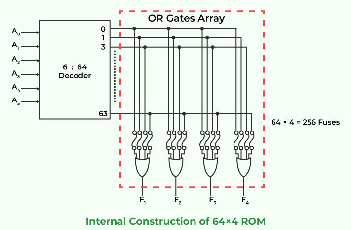
Figure-1: Read Only Memory
Types of ROM
ROM exists in various forms to suit different applications, including:
1. Mask ROM:
• Data is permanently written during the manufacturing process using masks.
• Once programmed, it cannot be modified.
• Used in large-scale applications where the data is finalized during production (e.g., consumer electronics).
2. Programmable ROM (PROM):
• Users can program PROM once after manufacturing using a PROM programmer.
• Data becomes fixed after programming.
• Suitable for applications where programming flexibility is needed after production.
3. Erasable Programmable ROM (EPROM):
• Allows data to be erased using ultraviolet (UV) light and reprogrammed.
• Widely used during development phases for testing and debugging.
4. Electrically Erasable Programmable ROM (EEPROM):
• Data can be erased and reprogrammed electrically without requiring UV light.
• Commonly used in devices that require data to be updated periodically (e.g., BIOS in computers).
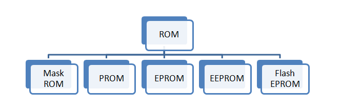
Figure-2: Types of ROM
Applications of ROM
• System Bootloaders: ROM stores the bootstrap loader,
a small program that initializes hardware components and loads
the operating system into RAM during startup. This ensures that
the system can start even without external storage.
• Firmware Storage: In embedded systems,
ROM stores firmware, which contains the fixed instructions
required for the device’s operation. Examples include washing
machines, microwaves, and automotive control systems.
• Control Units: ROM is used to store microinstructions
in the control units of computers, providing a fixed sequence of
operations for executing machine instructions.
• Lookup Tables: ROM is often employed to implement
lookup tables for operations like data conversion (e.g., ASCII to
binary), mathematical calculations (e.g., sine and cosine values),
and address decoding.
Structure of ROM
The internal structure of ROM is based on an array of memory cells
arranged in rows and columns. Each memory cell stores a bit of data,
represented as either a 0 or 1. The key components of ROM include:
• Memory Cells: Each cell is implemented
using transistors or diodes that define whether the stored
value is 0 or 1.
• Address Lines: Used to select specific memory locations. For an
n-bit address, 2n memory locations can be addressed.
• Decoder Circuit: Converts the binary address input
into a unique signal that activates the corresponding row of memory
cells.
• Data Lines: Output the binary data stored in the selected row.
• Control Signals: Control the enabling and
synchronization of read operations. Signals like Chip Enable
(CE) and Output Enable (OE) ensure that the correct memory
chip and operation mode are selected.
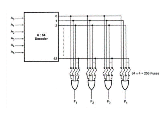
Figure-3: Structure of ROM
Working Mechanism
The operation of ROM can be divided into the following steps:
• Addressing: The binary address input is provided through the
address lines. This address specifies the location of the data to
be accessed.
• Decoding: The decoder circuit inside the ROM translates
the binary address into a unique row selection signal. This ensures
that only the corresponding row of memory cells is activated.
• Data Retrieval: Once the row is selected, the binary
values stored in its memory cells are sent to the output via the
data lines.
• Control Signals: The Chip Enable (CE) signal activates
the ROM chip, while the Output Enable (OE) signal enables the output
operation. These signals ensure proper timing and accuracy during the
read operation.
Conclusion
ROM is a vital non-volatile memory component in computer systems, used for storing essential data like firmware, system bootloaders, and control logic. This experiment provides a clear understanding of ROM's structure, working mechanism, and applications, demonstrating its importance in system initialization and embedded systems. By studying ROM, we recognize its role in ensuring consistent and reliable operation in digital systems.