
Theory
Introduction
A microprocessor communicates with external devices (e.g., sensors, memory) through an I/O interface. This interface manages the flow of data between the microprocessor and these devices, ensuring that data transfer occurs with proper timing and control.Flip-flops provide temporary data storage, while logic gates control data flow based on control signals (e.g., READ, WRITE, READY).
Control Signals
The interface uses control signals like READ, WRITE, READY, and ACK
(acknowledge) to manage the data exchange process. These signals help in
defining the operation mode (read or write) and synchronizing the microprocessor
with external devices.
• READ: A signal that indicates the microprocessor wants to receive data from an external device.
• WRITE: A signal that indicates the microprocessor wants to send data to an external device.
• READY: A signal from the external device that it is ready for data transfer.
• ACK: Acknowledgment signal indicating the completion of data transfer.
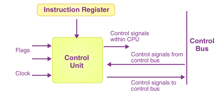
Figure-1: Control Signals
Data Bus
This is a set of parallel lines (typically 8, 16, or 32 bits) used for transferring data between the microprocessor and the device. During a READ or WRITE operation, data flows over this bus.
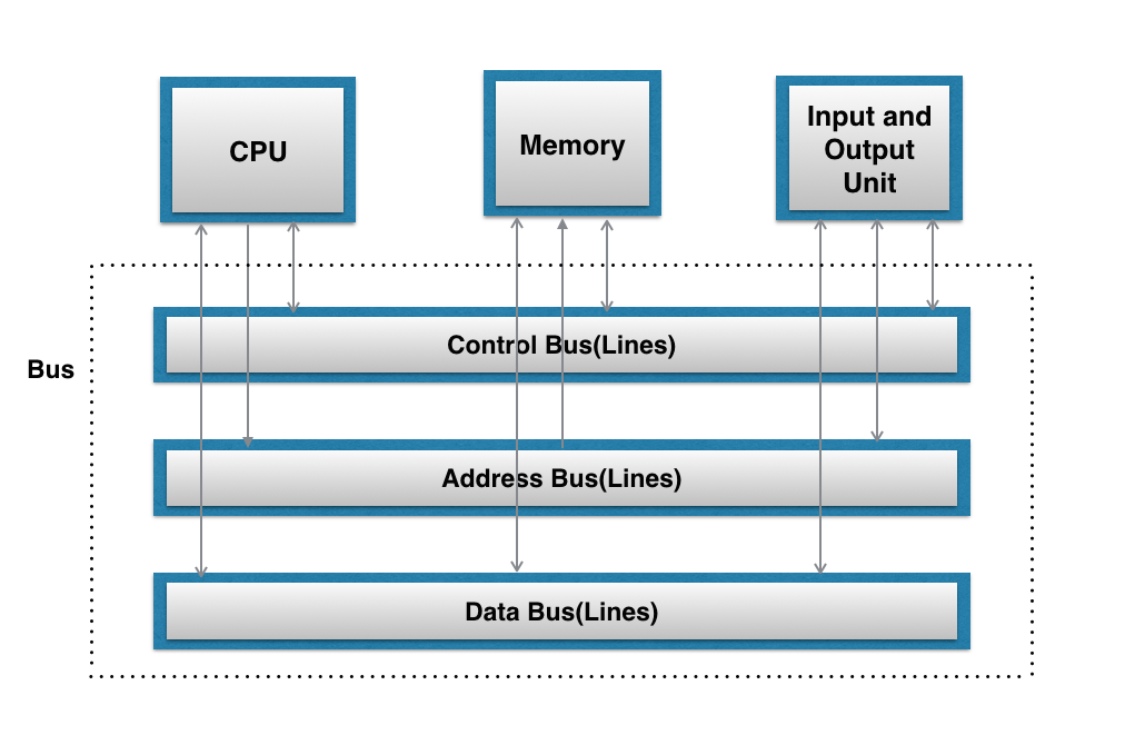
Figure-2: Data Bus
Clock Synchronization
A clock signal is used to synchronize the operations between the microprocessor and the devices. Clock pulses ensure that data transfer is timed accurately.
Flip-Flops in Digital Circuits
Flip-flops are the fundamental building blocks of registers and
memory elements in digital systems. A flip-flop is a bistable
multivibrator, meaning it has two stable states, which it can switch
between based on its input signals. Flip-flops are used to store
binary information, making them essential in registers, counters,
and other memory elements in microcontrollers.
• D Flip-Flop: A D flip-flop captures the input
data on the rising or falling edge of a clock signal, making it
ideal for building registers and synchronizing data storage.
• JK Flip-Flop: A more complex flip-flop used for
more flexible operations, including toggling and state control.
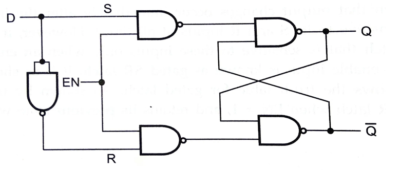
Figure-3: D-Flip Flop
Logic Gates
Logic gates perform basic logical operations on binary inputs and
produce a binary output. These gates (AND, OR, NOT, XOR, etc.) are
the fundamental elements that allow microcontrollers to process data
and make decisions.
• AND Gate: Outputs 1 only if both inputs are 1.
• OR Gate: Outputs 1 if at least one input is 1.
• NOT Gate: Outputs the opposite of the input
value.
• XOR Gate: Outputs 1 if only one input is 1, but
not both.
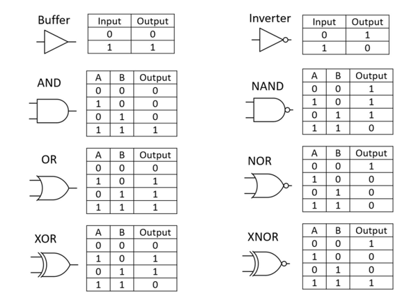
Figure-4: Logic Gates