
Procedure
- Step 1: Add Two D Flip-Flops
Navigate to the Components section and click on the D-Flip-Flop button to add two D flip-flops to the workspace.
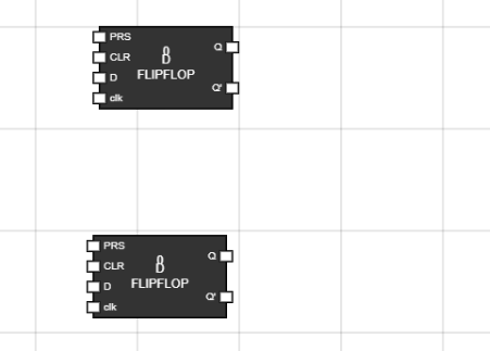
Figure 1: Two D Flip-Flops in Worspace - Step 2: Get Two Inputs for Both D Flip-Flops and Rename the Inputs
- For the first D flip-flop, go to the input component in Components section and press click to get the input in the workspace then press CTRL + A in the input of workspace to rename the input as Input1.
- For the second D flip-flop, go to the input component in Components section and press click to get the input in the workspace then pressCTRL + A to rename the input as Input2.
- For both flip-flops, take one more input component each and rename them as Clock.
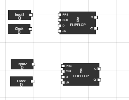
Figure 2: Inputs in workspace - Step 3: Connect Inputs to the D Flip-Flops
- For the first D flip-flop:
- Click on the white portion of Input1 to get a line (node) that can be connected.
- Drag the line and connect it to the D input of the first flip-flop.
- For the second D flip-flop:
- Click on the white portion of Input2 to get a line (node) that can be connected.
- Drag the line and connect it to the D input of the second flip-flop.
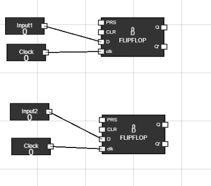
Figure 3: Connecting Inputs - Step 4: Add an OR Gate
- Select an OR gate from the Components section and place it on the workspace.
- Connect the Q output of the first flip-flop to one input of the OR gate.
- Connect the Q output of the second flip-flop to the second input of the OR gate.
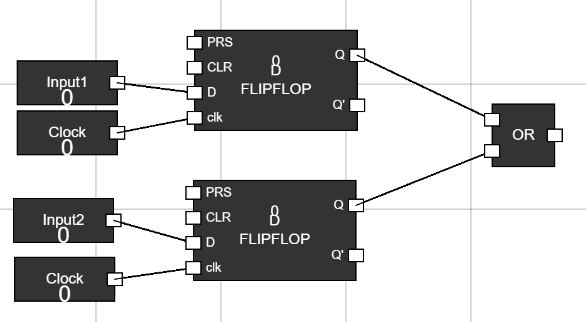
Figure 4: OR Gate Connected - Step 5: Connect the Output of OR gate to the D-input of Flip-Flops and connect clock
- Add one D flip-flop component from the Components section.
- Connect the output of the OR gate to the D-input of D flip-flop component, so the result from the OR gate can be stored in this D flip-flop. - Add one input component and connect it with the clk input of this new D flip-flop and rename that input as Clock using CTRL+A.
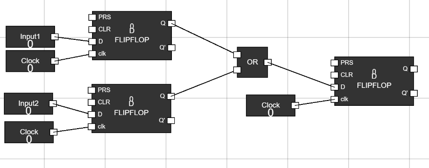
Figure 5: Connection with new flip-flop - Step 6: Add the new Output Component in workspace
- Add the new Output Component in the Workspace.
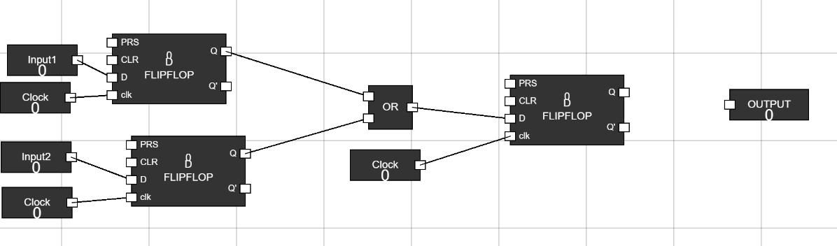
Figure 6: new Output component added - Step 7: Connect the Output Component with the Q output of D flip-flop
- Connect the Q output of D flip-flop with the new Output Component.
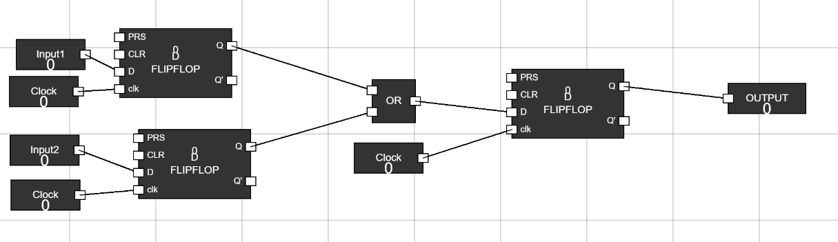
Figure 7: Connection with Output component - Step 8: Provide a Clock Input
- Click on the Clock input and set it to 1 to provide the clock signal in both the Flip-Flops.
- Now you can change the inputs and Observe changes in the output based on the behavior of the OR gate, as per its truth table.
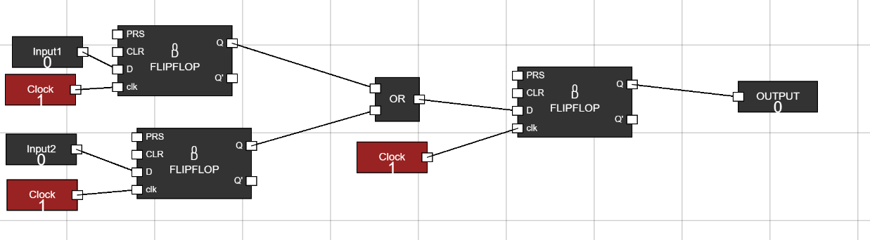
Figure 8a: Clock Input 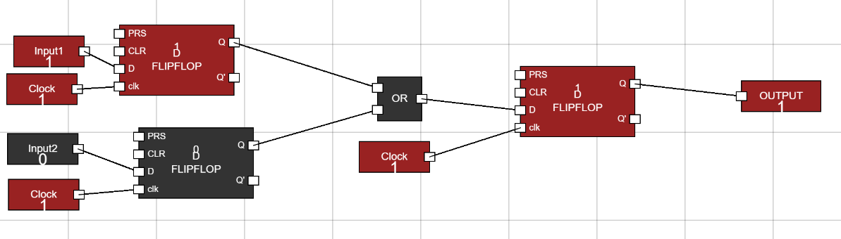
Figure 8b: Output value