
Introduction
Vapour compression cycle is a widely used refrigeration cycle. The main object of the test rig is to demonstrate a refrigeration system with basic components &
necessary controls.
The practical working of the system is demonstrated in a test rig and both theoretical as well as experimental performance analysis can be studied.
What is Refrigeration?
Refrigeration is defined as the process of removing heat from a body or enclosed space so that the temperature is first lowered and then maintained at level below
the temperature of the surrounding area. The equipment used to maintain the required temperature is called refrigerating equipment.
Types of Refrigeration system
There are two types of refrigeration system:
1. Vapour Compression Refrigeration system (VCRS)
2. Vapour Absorption Refrigeration system (VARS)
The Test Rig Set up
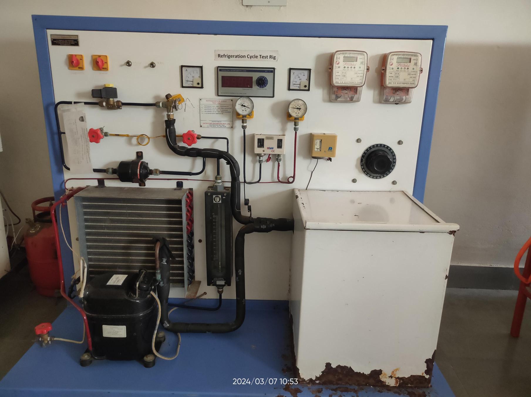
The test rig consists of a hermetically sealed compressor, evaporator, condenser, thermostatic expansion valve & capillary tube.
The condenser is air cooled for which a condenser fan and motor has been provided. Evaporator is a water immersion type which is housed in a thermally insulated tank.
In the system both thermostatic expansion valve & capillary tube is provided with the by-pass valve.
The refrigeration system can run either on the capillary tube or thermostatic expansion valve at a time.
Pressure gauges have been provided for indication of R-134a refrigerant pressures on suction side and discharge side of compressor.
The energy metres have been provided which indicates the power consumption of the compressor and heater.
The heater is provided with variac to vary the heating load on the evaporator and hence the temperature of water in evaporator.
The following are the main components of the cycle:
1. Compressor :
Compressor is the most important part of the system and it raises the pressure of incoming vapour from the evaporator pressure to condenser pressure.
Different types of compressors are:
(a) Reciprocating compressor
(b) Rotary compressor
(c) Screw compressor
(d) Centrifugal compressor
The selection of the above mentioned types of compressors depends on the usage.
Usually domestic refrigerators and air conditioners are installed with the reciprocating compressor.
A hermetic type compressor is one in which the compressor & motor integral on one shaft & they both are contained in a pressure sealed housing.
It is compact in size, quiet in operation, low in the cost & it has no problem with refrigerant gas leakage.
motor in a hermetic type compressor is cooled by refrigerant suction gas.
2. Evaporator :
The function of an evaporator is to remove heat from the product or the area to be cooled & to maintain at desired temperature.
The various types of construction of the evaporator used in the refrigerant system are:
(a) Finned tube evaporator coil
(b) Bare tube soldered/clamped to the tank
(c) Bare tube dipped in the liquid to be cooled
(d) Shell & coil type evaporator
The choice of particular construction depends on the type of appliance.
However in every case the heat capacity depends on three factors viz. temperature difference between the load & the refrigerant,
heat transfer coefficient & areas of the heat transfer.
3. Condenser :
The function of a condenser is to remove heat from the superheated high pressure
refrigerant vapour condenser from vapour to liquid. This is accomplished by a cooling medium either as air or water.
The air cooled condenser may be static cooled type where natural convective motion of air in surrounding is enough to cool
the condenser or it may be of the fan cooled type. The static cooled condensers are used in domestic refrigerators.
In commercial appliances the window and split air conditioners are usually provided with fan cooled condensers.
The water cooled condensers are normally used in large systems having capacity 5 tons and above.
4. Expansion Valve :
As the high pressure subcooled liquid refrigerant from the condenser passes through the expansion valve its
pressure and temperature is reduced and refrigerant comes out mostly in liquid state.
Following are the types of expansion valves:
(a) Thermostatic expansion valve:
Thermostatic expansion valve controls the mass flow rate of refrigerant by sensing evaporator outlet temperature.
Thus the valve is sensitive to the cooling load. If the load on the evaporator is more,
the degree of superheat of refrigerant coming out of the evaporator increases. To maintain the degree of
superheat to pre-set level more liquid is fed to the evaporator. When the evaporator load is low, the valve
closes which results in less liquid being fed to the evaporator.
(b) Capillary tube:
Capillary tube is the simplest and cheapest form of expansion device. It does not include any kind of moving parts hence no maintenance is required. Capillary tube is supposed to be a single point operation device in the sense that the best control is achieved only at a given set of operating parameters.
Under varying loads the capillary tube does not function satisfactorily e.g at lower loads than designed value capillary tube may overfeed the evaporator causing refrigerant liquid return to compressor. At higher loads than designed, the capillary tube starves the evaporator, causing excessive return gas superheat. Hence for large variations in cooling loads, capillary tube is not suitable.
5) H.P/L.P. cut out:
A high pressure cut out often called a pressure limiting device is a safety device which stops the compressor before head pressure goes
to excessively high values. This cut out is connected to the high pressure side of the system. It opens the circuit on rising pressure and closes on dropping pressure.
Some H.P cutouts have inter locks which when the circuit opens, must be manually reset to close the circuit. The L.P cut-out does the same function as the H.P cut out.
It is connected to the low side of the system and opens the circuit when the low side pressure decreases the pre-set value.
(6) Drier:
If by chance refrigerant is containing any water particle then in a low temperature region (i.e. at and after the expansion valve)it forms ice and chokes the valves or bends thereby preventing the smooth passage of refrigerant through it. To prevent this silica gel dryer is used to remove any water particles carried into the refrigerant.
(7) Solenoid valve:
In absence of this valve, the refrigerant in the high pressure line will have tendency to flow through the expansion valve because of pressure difference and get accumulated in the low pressure line. This situation will cause the starting trouble of the compressor. To prevent this, a solenoid valve is used which will operate automatically when the power supply to the compressor is cut-off and prevent the flow of refrigerant across it.
(8) Thermostat:
In any refrigerant plant, a particular temperature is required to be maintained to perform a particular job. A common method of controlling the temperature is starting and stopping of the compressor, by the use of simple temperature control is known as "Thermostat". A refrigerant or volatile fluid is in the control bulb. Vapour evaporated from this fluid exerts its vapour pressure in the flexible metallic bellows. Movement of bellows is opposed by a spring. An increase in the temperature of the liquid in the bulb increases pressure in the bellows and causes movement against the spring. The movement trips a toggle switch, which closes an electric contact to complete an electric circuit. A drop in temperature will open the contact. To control the temperature inside the refrigerator there is thermostat, whose sensor is connected to the evaporator. The thermostat setting can be done by the round knob inside the refrigerator compartment. When the set temperature is reached inside the refrigerator the thermostat stops the electric supply to the compressor and compressor stops and when the temperature falls below a certain level it restarts the supply to the compressor.
(9) Refrigerant:
The working substance used to make refrigeration is called the refrigerant. The refrigerant runs through all the inner parts of the refrigerator.
It is the refrigerant that carries out the cooling effect in the evaporator.
It absorbs the heat from the body to be cooled in the evaporator (chillier or freezer) and throws it to the atmosphere via condenser.
The refrigerant keeps on recalculating through all the inner parts of the refrigerator in cycle.
In the experiment we are going to use R-134a Refrigerant
Calculations
Observations from the experiment:
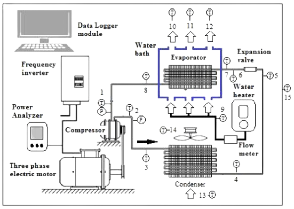
T5 = initial temperature
E1 = initial energy meter reading
E2 = final energy meter reading
T1 = temperature of refrigerant before compression
T2 = temperature of refrigerant after compression
T3 = temperature of refrigerant after condenser
T4 = temperature of refrigerant after expansion valve
P1 = gauge pressure before compression
P2 = gauge pressure after compression
t = duration of experiment
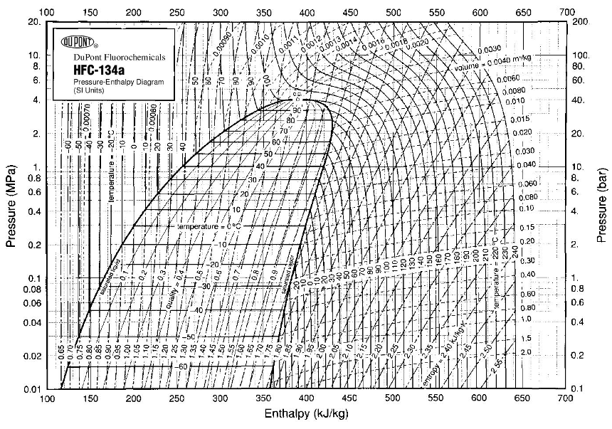
Read from p –h chart or property tables R 134 a, find the following enthalpies:
(1) h1 the enthalpy of the vapour entering the compressor
(2) h2 the enthalpy of the vapour leaving the compressor
(3) h3 the enthalpy of the after the condenser
(4) h4 the enthalpy of liquid after the expansion valve
A. Theoretical COP
Theoretical RE : (h1 - h4) kJ/Kg
Theoretical compressor power : (h2 - h1) kJ/Kg
COP = (h1 - h4) / (h2 - h1)
B: Actual COP:
Cooling capacity or the actual refrigeration effect REactual = heater energy consumption
REactual = (final reading - initial reading) / time taken (in hrs) kW
Work Done = energy consumed by the compressor
Work Done= (final reading - initial reading) / time taken (in hrs) kW
COPactual = REactual / Work Done