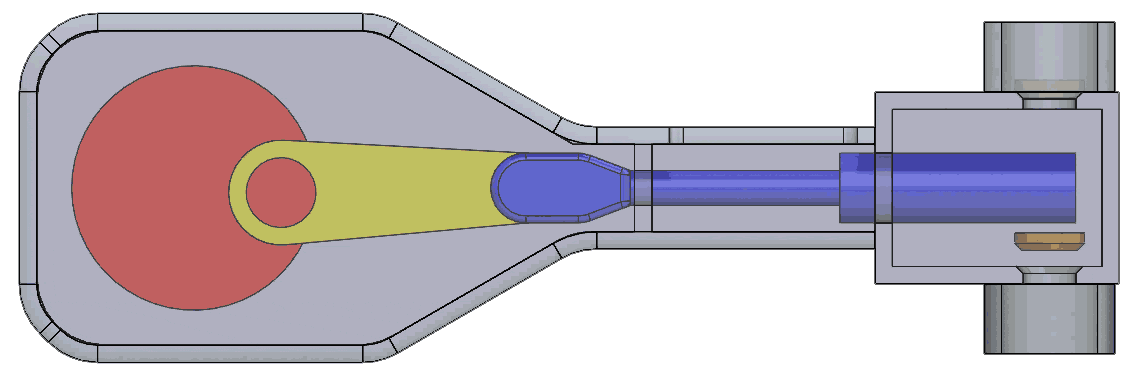
Compressor
Evaporator
Evaporator
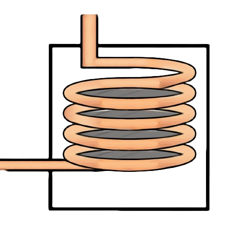
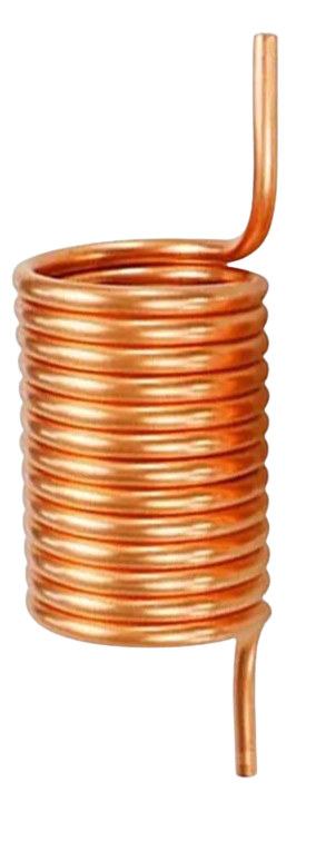
In refrigeration, an evaporator is the heat exchanger where the refrigerant circulating inside the refrigeration circuit absorbs the thermal energy from the environment, which is then cooled. This is how the state of the refrigerant changes from liquid to vapour, giving it its name. As a result, the refrigerant evaporates to absorb the temperature or energy from the environment to be cooled.
The main objective of an evaporator in a refrigeration system is to absorb heat from the surroundings, such as the air or water being cooled, and transfer it to the refrigerant, causing it to evaporate. This process cools the surroundings while allowing the refrigerant to become a gas, which is then compressed to begin the cycle again.

Condenser
Condenser
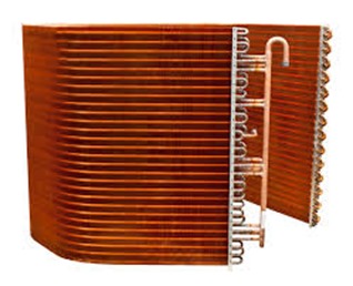
Condenser is found in general refrigeration systems. It serves to cool off the refrigerant sent from the Compressor which This refrigerant is a gas state with high temperature and pressure. Condenser works to cool down to condensate the refrigerant into a liquid. The temperature is lower but the pressure is still high.
The objective of a condenser in a refrigeration system is to release heat absorbed by the refrigerant in the evaporator, causing it to condense back into a liquid state. This process allows the refrigerant to release heat to the surrounding environment, thus completing the cycle and preparing the refrigerant to re-enter the evaporator.
Working of Condenser
1. Initially, high-temperature vaporised gas is introduced through a vapour inlet,
while coolant is introduced into the condenser shell through the coolant inlet.
2. As the high-temperature vapour traverses the tubes within the shell, it
undergoes a heat transfer process, releasing its heat to the surrounding coolant.
3. This heat exchange rapidly reduces the vapour's temperature along its path,
causing it to transition from a vapour state to a liquid state.
4. When the vapour temperature aligns with that of the coolant,
the condensation process concludes.
5. At this stage, the vapour is fully condensed, transformed into a liquid state, and
ready for use as feedwater, accessible through the condensate outlet.
Click Here For More Information
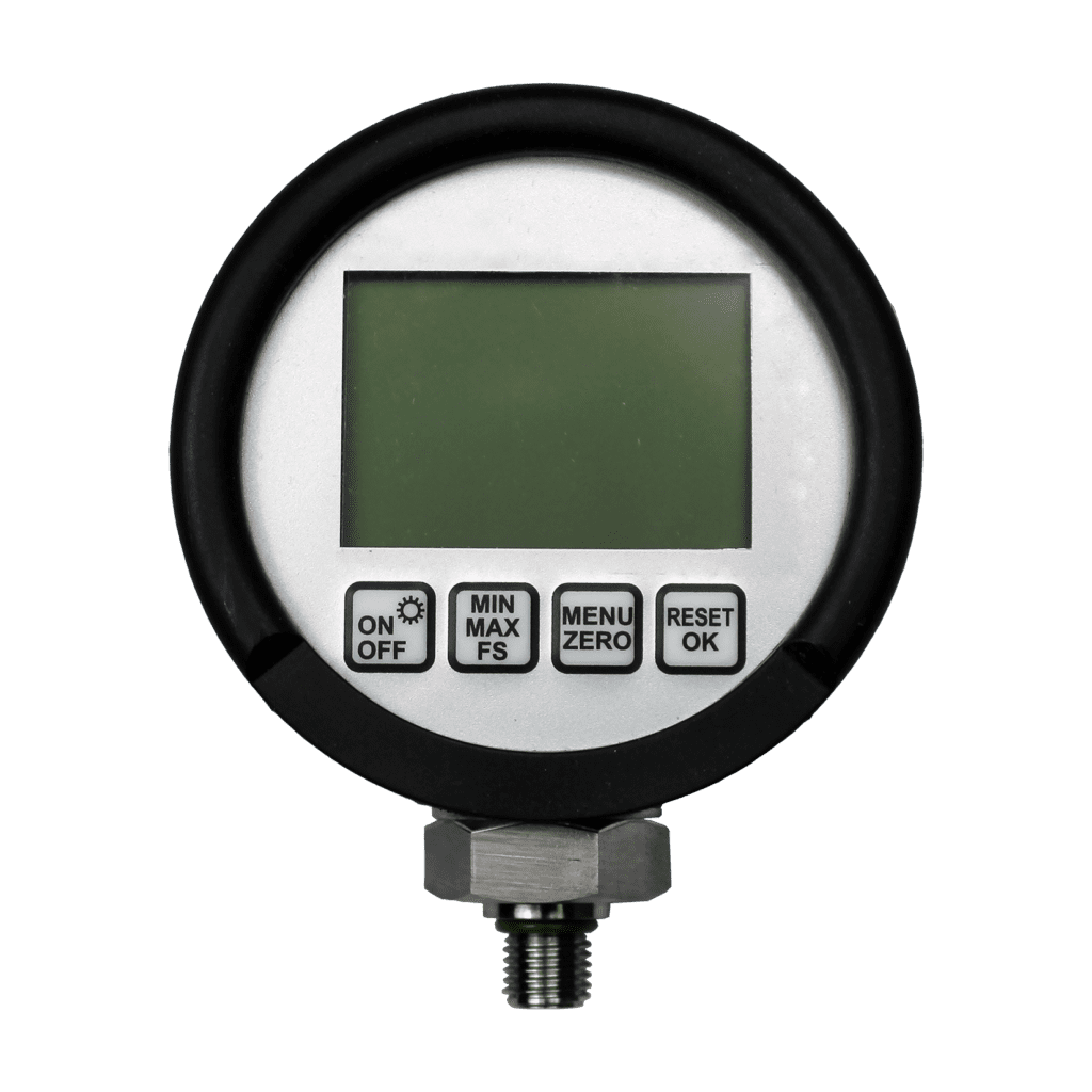
Pressure Gauge
Pressure Gauge
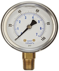
A pressure gauge is a mechanical instrument used to measure the pressure of a fluid (liquid or gas) within a system or container. It typically consists of a dial or digital display indicating pressure readings and a sensing element that detects the pressure exerted by the fluid.
Working of Pressure Gauge
Mechanical pressure gauges utilise an inner tube that is connected to a gear and
shaft assembly that work together to move a pointer. When the pressure within
the tube surges, the tube uncoils slightly. As the tube uncoils, the motion
triggers the gear and shaft system that moves the pointer on the gauge. The
amount of uncoiling movement that occurs is relative to the pressure within the
tube. This movement then informs the pointer, giving you a pressure reading.
Click Here For
More Information

Rotameter
Rotameter
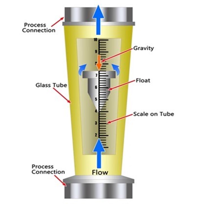
A rotameter is a device that measures the volumetric flow rate of fluid in a closed tube. It belongs to a class of meters called variable-area flow meters, which measure flow rate by allowing the cross-sectional area the fluid travels through to vary, causing a measurable effect.
The objective of a rotameter is to measure the flow rate of a fluid in a pipeline. It typically consists of a tapered tube with a float inside that rises as the flow increases. The position of the float within the tube indicates the flow rate, making it a simple and reliable device for measuring flow of water treatment.
Working of Rotameter
The operation of a rotameter is based on the variable area principle. That is,
the flow of a liquid raises the float inside a tapered tube, increasing the area
through which the liquid can pass. The larger the flow, the higher the float
will be raised. The level of the float is directly proportional to the flowrate of
the liquid, and it moves up or down in proportion to the liquid’s flowrate and
the annular area around the float. The tapered tube allows the annular area
between the ball and the tube to be proportionate to the flow, in a balanced
condition.
Expansion Valve
Expansion Valve
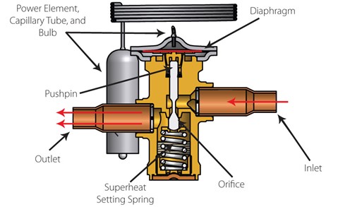
The expansion valve in a refrigeration system is a crucial component responsible for regulating the flow of refrigerant into the evaporator. Its main function is to control the amount of refrigerant entering the evaporator coils, thereby controlling the rate at which the refrigerant evaporates and absorbs heat from the surroundings.
The primary objective of the expansion valve in a refrigeration system is toprecisely control the flow of refrigerant into the evaporator. By regulating the amount of refrigerant entering the evaporator coils, the expansion valve ensures that the refrigerant evaporates at the desired rate, allowing for efficient heat absorption and effective cooling of the refrigerated space. This precise control helps maintain optimal performance and temperature conditions within the refrigeration system.
Working of Expansion valve
The expansion valve regulates the flow of refrigerant from the high-pressure side (condenser) to the low-pressure side (evaporator) in a refrigeration system. It operates based on the pressure difference between the two sides. When the refrigerant enters the expansion valve from the condenser side, its pressure is high. The valve restricts the flow, causing a pressure drop and allowing the refrigerant to expand rapidly as it enters the evaporator. This expansion leads to a decrease in temperature, enabling the refrigerant to absorb heat from the surroundings inside the evaporator, thus cooling the space or object being refrigerated.
Energy Meter
Energy Meter
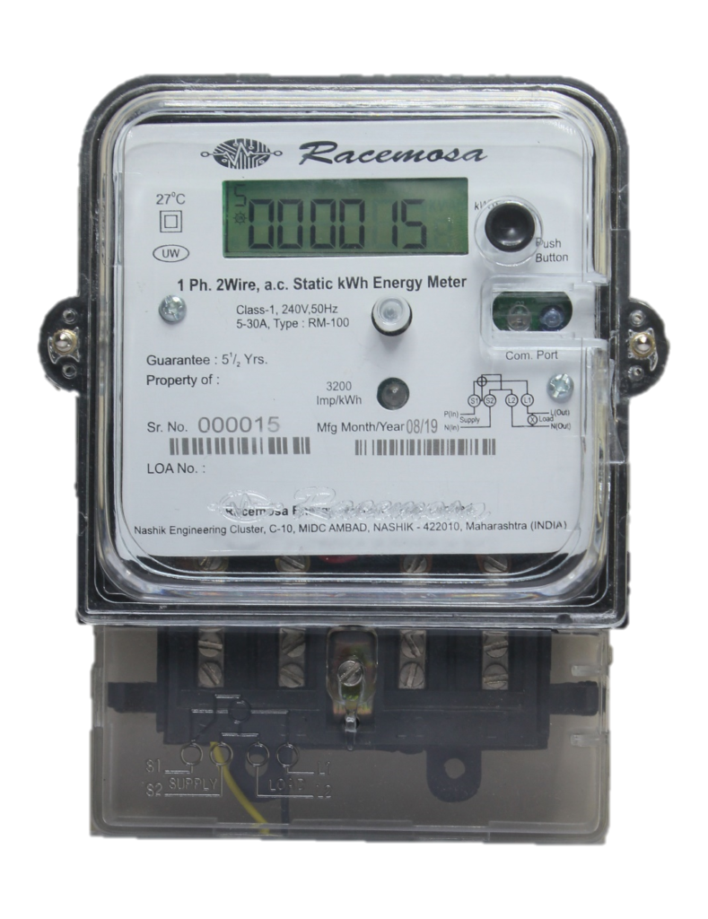
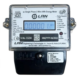
An energy meter, also known as an electricity meter or watt-hour meter, is adevice used to measure the amount of electrical energy consumed by a residence, business, or other electrical load over a specific period. It typically measures the amount of energy in kilowatt-hours (kWh) or other appropriate units. Energy meters are essential for billing purposes, energy management, and monitoring electrical consumption. They come in various types, including electromechanical, electronic, and smart meters, each offering different features and capabilities.
The objective of using an energy meter in a refrigeration system experiment is to measure the energy consumption of the system accurately. This helps in understanding the efficiency of the refrigeration system, identifying areas for improvement, and optimizing energy usage to reduce operational costs.
Click Here For More Information
Voltmeter
Voltmeter
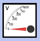
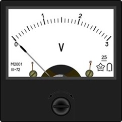
The objective of using a voltmeter in a refrigeration system experiment is to measure the electrical voltage across various components such as the compressor, condenser, evaporator, and other electrical elements. This helps in assessing the performance and efficiency of the system, diagnosing any electrical issues, and ensuring safe operation.
Working of voltmeter
A voltmeter works by measuring the voltage difference between two points in an electrical circuit. It typically consists of a sensitive meter, which may be analog or digital, and leads or probes that are connected to the points where the voltage is to be measured. When the voltmeter is connected correctly, it displays the voltage reading in volts, allowing the user to assess the electrical potential difference across the circuit components. This measurement helps in troubleshooting, testing, and monitoring electrical systems.
Click Here For More Information
Ammeter
Ammeter
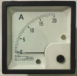
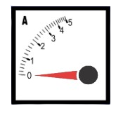
An ammeter is an instrument used to measure electric current in a circuit. It is typically connected in series with the circuit under test so that the current flows through the meter. Ammeters are designed to have very low resistance so as not to significantly affect the circuit being measured.
Working of Ammeter
The working principle of an ammeter in a vapor compression system involves
measuring the electrical current flowing through the compressor motor.
1. Installation: The ammeter is connected in series with the electrical circuit that
powers the compressor motor. This means that the current flowing through the
compressor motor also flows through the ammeter.
2. Current Measurement: As the compressor motor operates, it draws electrical
current from the power supply to power its operation. The ammeter measures
this current by detecting the magnetic field generated by the flow of current
through its internal components.
3. Display: The ammeter displays the measured current either on an analog scale
or digitally, depending on the type of ammeter being used. The reading
indicates the amount of electrical current flowing through the compressor
motor at any given time.
4. Monitoring and Analysis: Technicians or operators monitor the ammeter
readings to ensure that the compressor motor is operating within its normal
operating range. Abnormalities in the current reading, such as sudden spikes
or drops, can indicate potential issues with the compressor motor, electrical
connections, or other components in the system.