
Theory
Introduction:
The word DC is basically an abbreviation of Direct current. So, a direct current motor is commonly used motor having two input terminals, one is positive and the other one is negative. If we connect these terminals with the voltage supply the motor will rotate. If you change the polarity then motor will rotate in opposite direction. DC motor has a lot of applications. You can use it in automation projects, for controlling static as well as mobile robots, in transport system, in pumps,fans,bowers and for industrial use as well. In this Experiment, We will do the DC Motor Direction Control using an Arduino, L293D motor driver, potentiometer, and push button.
L293D Motor Driver:
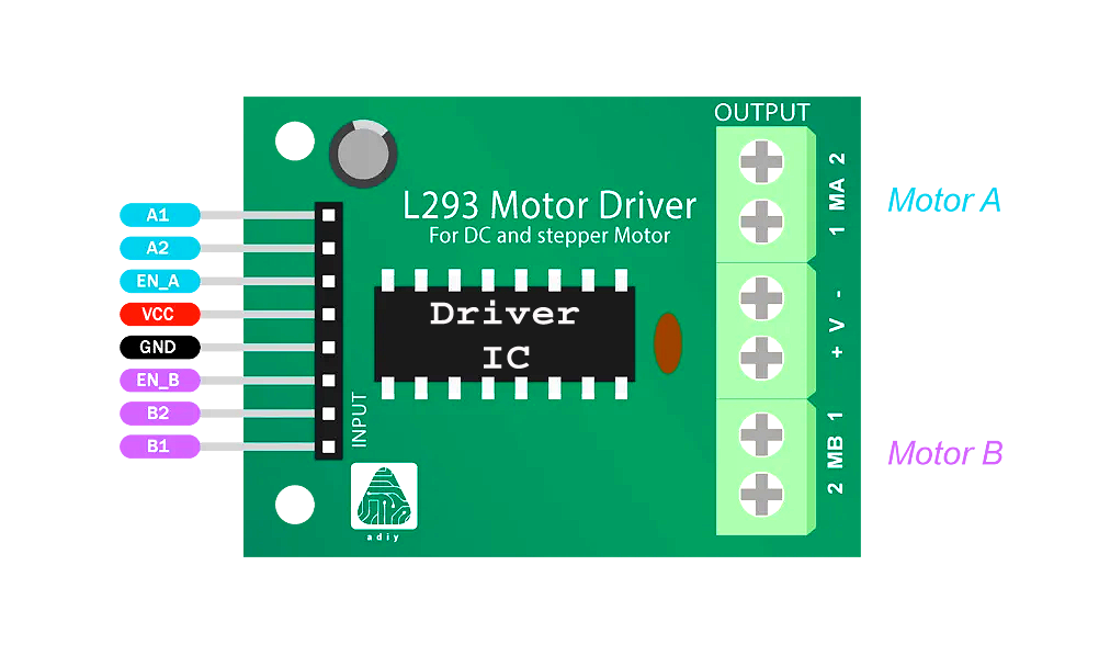
The L293D is an integrated circuit designed specifically to control the direction and speed of DC motors. It contains two H-bridges, which are arrangements of transistors that allow bidirectional current flow. Each H-bridge consists of four switches that can be independently controlled to determine the polarity of the voltage applied to the motor terminals. By toggling these switches, the L293D can drive the motor forward, backward, or stop it altogether. Additionally, the L293D can handle higher currents than the Arduino's GPIO pins, making it suitable for driving motors with higher power requirements.
Key Features of L293D Motor Driver :
1. Dual H-Bridge Design: The L293D boasts a dual H-bridge configuration, which essentially means it can control two motors independently. This feature is particularly valuable in scenarios where precise control over multiple motors is required. For instance, in robotics applications, you may need to control the movement of two wheels independently to navigate obstacles or execute complex maneuvers.
2. Bidirectional Control: One of the standout features of the L293D is its ability to facilitate bidirectional control of DC motors. This means you can not only drive the motors forward but also reverse their direction of rotation with simple logic inputs. This bidirectional control capability is indispensable in robotics and automation projects where the ability to maneuver in both directions is essential for achieving desired outcomes.
3. High Current Capability: The L293D is designed to handle significant current loads, making it suitable for driving a wide range of motors. With a continuous current rating of up to 600mA per channel and peak currents of up to 1.2A per channel, this motor driver can power motors of varying sizes and specifications. Whether you're working with small hobby motors or larger industrial-grade motors, the L293D has you covered.
4. Built-in Diodes: Integrated flyback diodes within the L293D serve a crucial role in protecting the motor driver and connected components from voltage spikes that occur during motor operation. These diodes provide a path for the dissipation of back electromotive force (EMF), ensuring that potentially damaging voltage spikes are safely redirected away from sensitive circuitry. This built-in protection enhances the reliability and longevity of the L293D and the overall system in which it is employed.
5. Simple Interface: The L293D's user-friendly interface simplifies the process of integrating it into your circuits. With minimal external components required for operation, you can focus on implementing your motor control logic without being bogged down by complex circuitry. This simplicity not only streamlines the development process but also reduces the overall complexity of your system, making maintenance and troubleshooting more manageable.
6. Wide Voltage Range: Operating efficiently within a wide voltage range of 4.5V to 36V, the L293D is incredibly versatile and adaptable to various power supply configurations. Whether you're working with battery-powered devices or mains-powered equipment, the L293D can accommodate your voltage requirements, making it suitable for a broad spectrum of applications spanning from low-power hobby projects to high-performance industrial systems.
Applications of L293D Motor Driver:
The L293D Motor Driver finds application in a diverse range of projects, including:
1. Robotics: In the realm of robotics, the L293D Motor Driver plays a pivotal role in controlling the movement of various components, including wheels, arms, grippers, and other actuators. Whether you're building a mobile robot, a robotic arm, or a humanoid robot, the L293D enables precise control over the speed and direction of motors, allowing your creations to navigate environments, manipulate objects, and perform tasks autonomously or under human supervision.
2. Automation: Industrial automation relies heavily on motor control for driving conveyor belts, pumps, fans, actuators, and other machinery. The L293D Motor Driver's ability to provide bidirectional control and handle high current loads makes it an excellent choice for automating processes in manufacturing plants, warehouses, and industrial facilities. With its robust performance and reliability, the L293D ensures smooth and precise operation, enhancing efficiency and productivity in automated systems.
3. DIY Electronics: Enthusiasts and hobbyists in the DIY electronics community often turn to the L293D Motor Driver to power their remote-controlled cars, boats, drones, and other projects. Whether you're building a small-scale RC vehicle for leisurely outdoor adventures or embarking on ambitious aerial drone projects, the L293D offers the flexibility and power necessary to drive motors of varying sizes and specifications. Its simplicity of use and wide voltage range make it accessible to beginners while still catering to the needs of experienced makers.
4. Educational Projects: The L293D Motor Driver serves as an invaluable educational tool for students and educators alike, offering hands-on learning opportunities in motor control, electronics, and robotics. Through experimentation with the L293D, students can explore fundamental concepts such as PWM (Pulse Width Modulation), motor speed control, H-bridge operation, and logic-level interfacing. Whether as part of classroom activities, robotics clubs, or individual projects, the L293D fosters curiosity, creativity, and problem-solving skills in learners of all ages.
DC Motor:
What is a DC Motor?
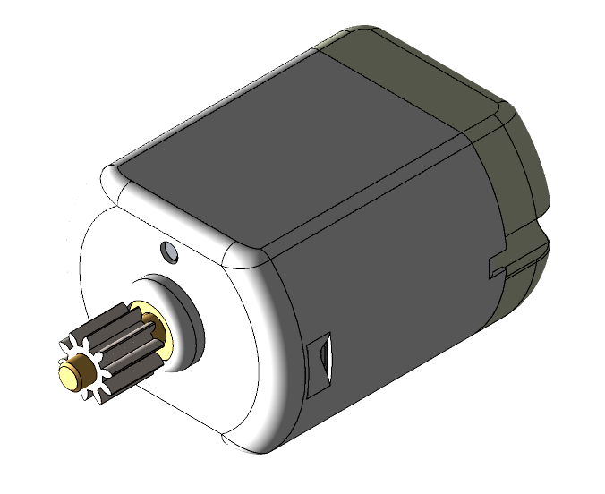
The DC motor is the electromechanical device responsible for converting electrical energy into rotational motion. It consists of a rotor (the rotating part) and a stator (the stationary part) with windings. When current flows through the windings, a magnetic field is generated, interacting with the magnetic field of the motor's permanent magnets to produce torque, causing the rotor to rotate. By controlling the voltage and polarity applied to the motor terminals, the speed and direction of rotation can be manipulated.
Construction and components of a DC Motor:
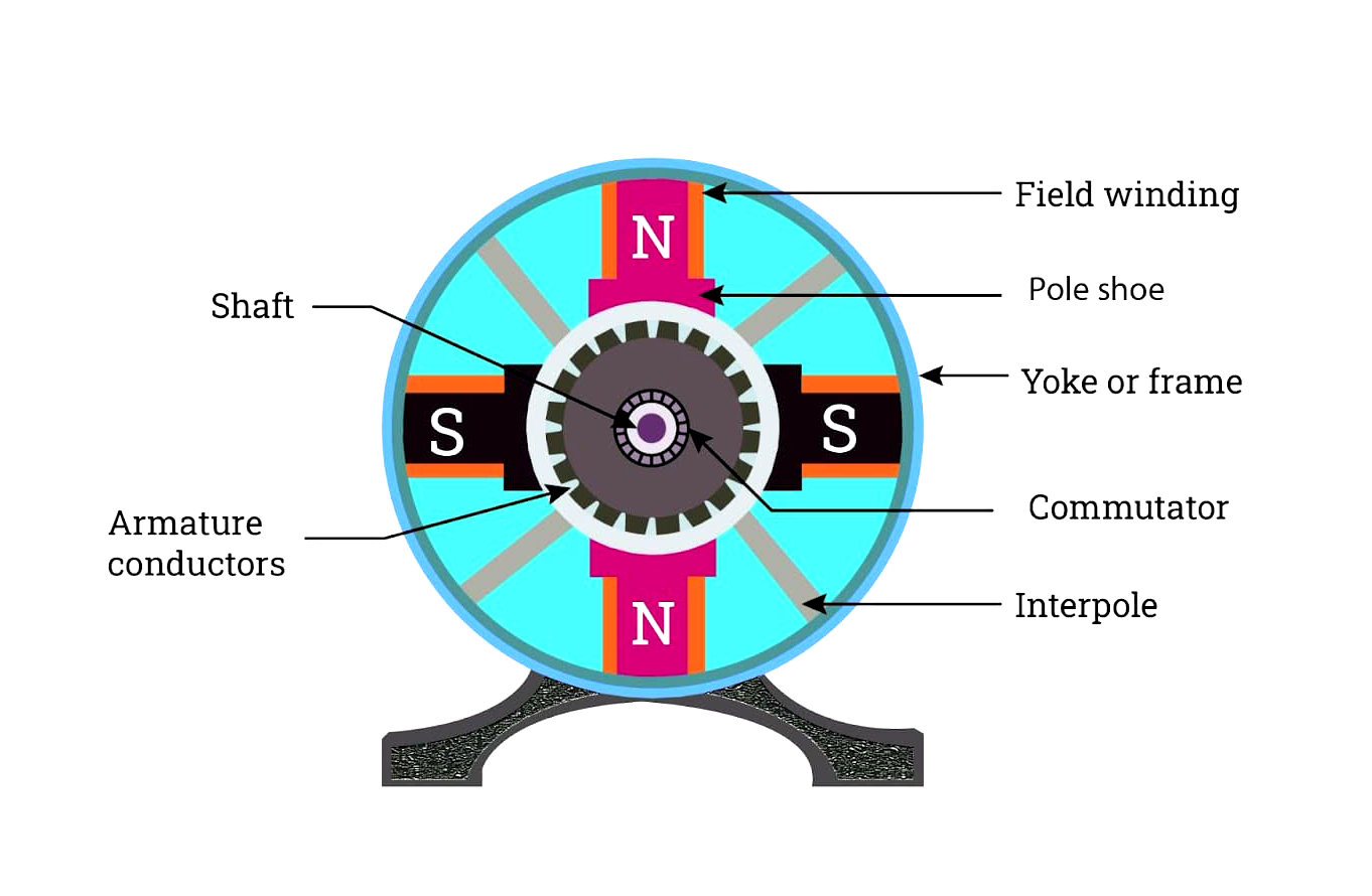
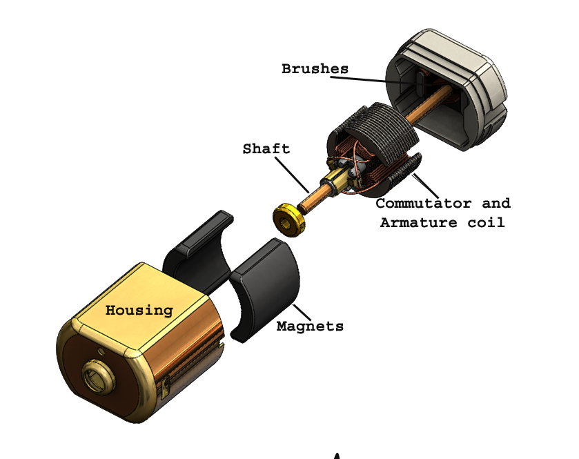
A DC motor's construction typically consists of several key components. The main parts include a stator, which houses a permanent magnet or electromagnet that generates a static magnetic field. Inside the stator is a rotor, usually made up of a coil of wire called the armature, which is mounted on an axle. When an electric current is applied to the armature, it becomes an electromagnet, interacting with the stator's magnetic field. This interaction creates a torque that causes the rotor to rotate, resulting in mechanical motion. Additionally, a commutator and brushes facilitate the flow of current to the armature, ensuring continuous rotation.
Following is the discription of components:
1. Stator: The stator is the stationary part of the DC motor and consists of a magnetic frame or core made of laminated steel sheets. These sheets are stacked to reduce eddy current losses. The stator contains the field windings, which produce the magnetic field that interacts with the rotor to generate motion.
2. Rotor: The rotor is the rotating part of the DC motor and is located inside the stator. It typically consists of a shaft mounted with a cylindrical armature core made of laminated steel sheets. Conductors, usually copper wires, are wound around the armature core to form multiple coils. These coils are connected to the commutator segments.
3. Commutator: The commutator is a cylindrical device mounted on the rotor shaft and consists of multiple insulated segments. Each segment is connected to the ends of the armature coils. The commutator reverses the direction of current flow in the armature coils as the rotor rotates, ensuring that the torque produced by the motor remains in a constant direction.
4. Brushes: The brushes are stationary carbon or graphite blocks that make electrical contact with the commutator segments. They transfer electrical power from the external power source (such as a battery or power supply) to the armature coils as the commutator rotates. Brushes are positioned within the motor housing and are typically spring-loaded to maintain constant contact with the commutator.
5. Bearings: Bearings are used to support the rotor shaft and reduce friction between moving parts. Typically, DC motors employ ball bearings or sleeve bearings to ensure smooth rotation of the rotor. Bearings are positioned at both ends of the motor housing and are designed to withstand radial and axial loads.
6. Housing: The housing, also known as the frame or casing, encloses the internal components of the DC motor and provides structural support and protection. It is usually made of durable materials such as aluminum, steel, or plastic. The housing also contains cooling vents or fins to dissipate heat generated during motor operation.
Operation of a DC motor:
The operation of a DC motor hinges on the conversion of electrical energy into mechanical motion through electromagnetic interactions. When electrical power is supplied to the field windings within the stationary stator, it creates a magnetic field. This field interacts with the magnetic field generated by the armature coils housed within the rotor, inducing electromagnetic torque. This torque exerts a rotational force on the rotor, causing it to spin. As the rotor rotates, the commutator ensures the continuous flow of electrical current to the armature coils, reversing the direction of current flow at specific intervals to maintain consistent rotation in a single direction. This continuous interplay of magnetic fields and electrical currents enables the DC motor to efficiently convert electrical energy into mechanical energy, providing reliable and precise motion control for a diverse range of applications.
Applications of DC Motor:
The DC motors find application across a diverse array of industries and sectors, including:
1. Robotics and Automation: DC motors play a pivotal role in robotics and automation systems, where precise motion control is essential. They drive wheels for mobility, actuate robotic arms and manipulators for assembly tasks, and power various actuators for gripping, lifting, and positioning objects. Whether in industrial settings, commercial environments, or educational institutions, DC motors enable the efficient and reliable operation of robotic platforms for a multitude of purposes.
2. Transportation: In the realm of transportation, DC motors contribute to the advancement of electric vehicles (EVs), drones, scooters, bicycles, and more. They provide the propulsion necessary for these vehicles to move efficiently and quietly, offering eco-friendly mobility solutions that reduce reliance on fossil fuels. From compact electric scooters for urban commuting to large-scale EVs for public transportation, DC motors drive innovation in the transportation sector.
3. Aerospace and Defense: DC motors are integral components in aerospace and defense applications, where reliability, performance, and precision are paramount. They maneuver actuators and control surfaces in aircraft for flight control, adjust propulsion systems in satellites and spacecraft for orbital maneuvers, and power propulsion systems in drones and military vehicles for navigation and operation. DC motors contribute to the safety, efficiency, and effectiveness of aerospace and defense operations.
4. Home and Building Automation: DC motors enable automation and convenience in homes and buildings by operating gates, shutters, blinds, HVAC (heating, ventilation, and air conditioning) systems, and smart home appliances. They open and close gates and shutters for security and privacy, adjust blinds and curtains for light control and energy efficiency, regulate airflow and temperature in HVAC systems for comfort, and power smart appliances for remote control and automation. DC motors enhance comfort, convenience, and energy efficiency in residential and commercial spaces.
5. Medical Devices: In the healthcare industry, DC motors drive a variety of medical devices and equipment critical for patient care and treatment. They power pumps for drug delivery, ventilators for respiratory support, prosthetics for mobility assistance, and medical imaging equipment for diagnostic purposes. DC motors enable precise control and operation of medical devices, enhancing healthcare outcomes and improving patient quality of life.
Circuit for Interfacing of the DC Motor with Arduino:
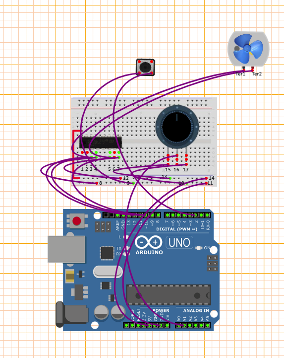
Working of the Circuit:
1. Pin Configuration (setup()):
• relay_pin and led_pin
are defined as variables representing the Arduino pin numbers connected to the relay module and an LED, respectively.
• pinMode() is used to configure these pins:
- relay_pin is configured as an output pin, indicating it controls the relay module.
- led_pin is configured as an output pin, likely to indicate the status of the relay operation.
- enablePin is configured as an output pin, which controls the motor speed through PWM (Pulse Width Modulation).
- statusPin is configured as an output pin, possibly to indicate the status of the motor.
2. In the loop() function:
• digitalWrite(statusPin, HIGH);
sets the statusPin high, possibly indicating the motor is in operation.
• int speed = analogRead(potPin) / 4;
delays for 2 microseconds.
• digitalWrite(trig_pin, HIGH);
reads the analog input from potPin (potentiometer) and maps it to a speed value. The value read is divided by 4, possibly for scaling purposes.
• boolean reverse = digitalRead(switchPin);
reads the state of switchPin, determining whether the motor should rotate in the forward or reverse direction.
• setMotor(speed, reverse);
is called with the speed and direction parameters obtained, which sets the motor speed and direction accordingly.
• duration = pulseIn(Echo_pin, HIGH);
measures the duration of the pulse received by the Echo_pin.
• distance = duration * 0.034 / 2;
calculates the distance based on the duration of the pulse (speed of sound is approximately 34 cm/ms, hence divided by 2 for round-trip distance).
3. setMotor Function:
• analogWrite(enablePin, speed);
sets the speed of the motor by applying a PWM signal to the enablePin.
• digitalWrite(in1Pin, !reverse);
sets the direction of the motor by controlling the state of in1Pin. If reverse is false, it sets in1Pin high (forward direction), otherwise low (reverse direction).
• digitalWrite(in2Pin, reverse);
sets the direction of the motor by controlling the state of in2Pin. If reverse is false, it sets in2Pin low (forward direction), otherwise high (reverse direction).
In summary, this code allows the user to control the speed and direction of a DC motor using a potentiometer and a switch connected to an Arduino board. The motor speed is adjusted based on the analog input from the potentiometer, and its direction is determined by the state of the switch.