
Theory
Introduction to Wien's Bridge
Wien's bridge is an AC electrical circuit widely used for the measurement of capacitance with high accuracy and can also be used for measuring frequency. The circuit consists of four arms, two arms with a series combination of resistors and capacitors and the other two arms have resistors. The circuit diagram of Wien's bridge is shown below:
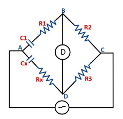
Fig.1 Wien's Bridge
A balance detector or null indicator is connected across two junctions (i.e., across BD as shown above). The indicator shows null deflection when the bridge is balanced, i.e., when the junctions B and D will be at the same potential.
Let \( Z_1 \), \( Z_2 \), \( Z_3 \), and \( Z_4 \) be the impedances of the arm AB, BC, CD, and AD respectively, and given as-
\( Z_2 = R_2 \)
\( Z_3 = R_3 \)
\( Z_4 = R_x + \frac{1}{j\omega C_x} \)
When the bridge is balanced, we have,
\( \frac{R_2}{R_3} = \frac{R_1 + \left (\frac{1}{j\omega C_1} \right )}{R_x + \left (\frac{1}{j\omega C_x} \right )} \)
\( R_2 R_x + \left (\frac{R_2}{j\omega C_x} \right ) = R_1 R_3 + \left (\frac{R_3}{j\omega C_1} \right ) \)
Now, Equating the Real and Imaginary terms,
\( R_x = \frac{R_1 R_3}{R_2}…. (1) \)
\( \frac{R_2}{j\omega C_x} = \frac{R_3}{j\omega C_1} \)
\( \frac{R_2}{C_x} = \frac{R_3}{C_1} \)
\( C_x = \frac{C_1 R_2}{R_3}.... (2) \)
The above equations are used to determine the unknown resistance and capacitance respectively.
Applications of Wien's Bridge:
- Wien's bridge is used for measurement of capacitance in terms of resistance and frequency.
- It can also be used to measure audio frequencies.
- The Wien’s bridge is suitable for the measurement of frequency of the range of 100Hz to 100kHz.