Procedure
Step 1. Click on the Control Circuit button in Control Circuit Section.
Step 2.Get the required components in Control Circuit Section by clicking on components displayed in Components Section.
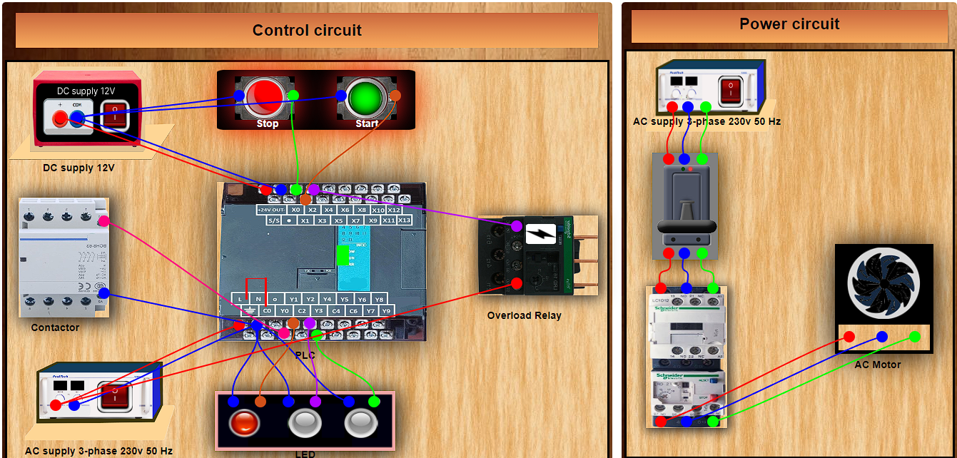
Step 3.Establish the connections according to the control circuit diagram provided in Fig. (a).
Step 4. Verify the control circuit by clicking on the Check Connections 1 button.
Step 5.If Wrong Connections, click on the Delete Connections 1 button to delete connections and make the right connections.
Step 6.Once the Control Circuit is verified, click on the PLC to design the ladder logic.
Step 7.A new window will appear for the ladder logic. Design the ladder logic using the instructions tab on the PLC window.
Step 8.Once the ladder logic is verified, switch to the Power Circuit Section. Make the connections according to the Power Circuit diagram provided in Fig. (b).
Step 9.Click on the Check Connections 2 button to validate the Power Circuit.
Step 10.If Wrong Connections, click on the Delete Connections 2 button to delete connections and make the right connections.
Step 11. Once the Power Circuit is verified, switch on the Power Supplies & enable the Start Button by a clicking on them.
Step 12. To stop circuit click on the Stop button.
Step 13. To overload the current click on the ⚡ button which is located at the Overload relay.
Step 14. Click on the Print button to get a print of the webpage.
Step 15. Click on the Reset button to refresh the webpage.