Procedure
Step 1 : Click on the Control Circuit button in Control Circuit Section.
Step 2 : Get the required components in Control Circuit Section by clicking on components displayed in Components Section.
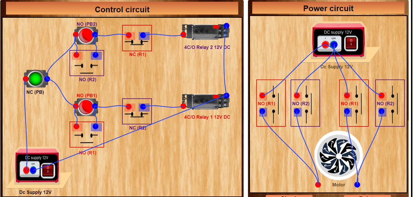
Step 3 : Establish the connections according to the control circuit diagram provided in Fig. (a).
Step 4 : Verify the control circuit by clicking on the Check Connections 1 button.
Step 5 : If Wrong Connections then click on Delete Connections 1 button to delete connections and make the right connections .
Step 6 : Once the Control Circuit is verified, switch to the Power Circuit Section.
Step 7 : Get the required components in Power Circuit Section by clicking on components displayed in Components Section.
Step 8 : Make the connections according to the Power Circuit diagram provided in Fig. (b).
Step 9 : Click on the Check Connections 2 button to validate the Power Circuit Connection.
Step 10 : If Wrong Connections then click on Delete Connections 2 button to delete connections and make the right connections .
Step 11 : Once the Power Circuit is verified, Switch On the Power Supplies.
Step 12 : Click on the NO Push Button 1 to rotate the motor anticlockwise .
Step 13 : Click on the NC Push Button to stop the rotation the motor .
Step 14 : Click on the NO Push Button 2 to rotate the motor clockwise .
Step 15 : Click on the Print button to get a print of the webpage.
Step 16 : Click on the Reset button to refresh the webpage .