
Theory
A Brushless DC (BLDC) motor is a type of synchronous machine that combines the benefits of permanent-magnet excitation with electronic commutation. Unlike brushed DC motors, BLDC motors do not use mechanical brushes; instead, they rely on a three-phase inverter that synthesizes AC waveforms from a DC supply to energize the stator windings.
2. Theory of Operation
2.1 Three-Phase Inverter
The three-phase inverter consists of six switching devices (e.g., MOSFETs or IGBTs) arranged in three legs. By turning these switches on and off in a predetermined sequence, the inverter converts the DC input into three phase-shifted AC voltages (typically 120° apart).
2.2 Switching Patterns
The static or “six-step” commutation pattern is one of the simplest control schemes. In this approach, only two phases are energized at any given time, and the conduction sequence rotates through all six states in one electrical cycle:
- Phase A positive, Phase B negative
- Phase A positive, Phase C negative
- Phase B positive, Phase C negative
- Phase B positive, Phase A negative
- Phase C positive, Phase A negative
- Phase C positive, Phase B negative
3. Experimental Setup
The following components and instrumentation are used in the setup:
- DC Power Supply: Provides the input voltage to the inverter.
- Three-Phase Inverter: Contains six transistors arranged in three half-bridges.
- BLDC Motor: A three-pole permanent-magnet motor rated for the chosen voltage and speed range.
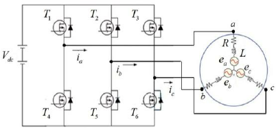
Figure 1: Schematic of the BLDC motor drive with inverter.
4. Working Procedure
- Apply DC Supply: Switch on the DC source to energize the inverter bridge.
- Initiate Commutation: Send the predefined six-step switching sequence to the inverter’s gate driver.
- Generate Three-Phase AC: The inverter synthesizes three 120°-shifted voltages which flow through the stator windings in sequence.
- Rotor Motion: The rotating magnetic field produced by the stator interacts with the rotor’s permanent magnets, causing continuous rotation.
5. Observations and Measurement
Analyze the collected waveforms to ensure that commutation timing aligns with rotor position, minimizing torque ripple.
6. Conclusion
In this experiment, a BLDC motor was successfully driven using a static six-step commutation pattern. The three-phase inverter effectively converted DC to AC, producing a rotating magnetic field that kept the rotor in synchrony with the stator’s excitation. The ideal rotational sensor provided accurate feedback on angular velocity and position, demonstrating the importance of precise timing in minimizing torque ripple and ensuring smooth operation.