
Introduction
A Permanent Magnet Synchronous Motor (PMSM) is a type of synchronous motor that uses permanent magnets embedded in or mounted on the rotor to create the required magnetic field. Unlike induction motors, PMSMs do not rely on rotor current for magnetism, resulting in higher efficiency, faster dynamic response, and better control over speed and torque.
These motors are commonly controlled using inverter-based drives that apply advanced control techniques like Field-Oriented Control (FOC), enabling precise and independent control of torque and flux. The performance of the PMSM motor drive is evaluated by analyzing how it responds to varying load conditions in terms of current, speed, and torque.
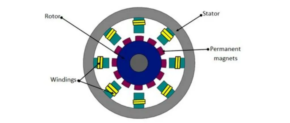
fig.1 : PMSM Motor
Working Principle
• A rotating magnetic field is generated by applying a 3-phase AC current to the stator.
• The rotor, which contains permanent magnets, locks into synchronism with the stator field and rotates at
the same speed.
• No slip occurs between the rotor and stator fields, unlike induction motors.
• A controller adjusts the inverter output (voltage and frequency) based on real-time feedback to maintain
desired performance.
Performance Parameters
• Load vs Current: As load increases, the motor draws more current to maintain speed and
torque. Initially, current increases linearly; beyond a point, a sharp rise is observed due to increased
torque demand.
• Speed: The motor maintains a nearly constant speed due to closed-loop control systems,
demonstrating excellent speed regulation.
• Torque: Generated torque is proportional to the q-axis current in the FOC control
strategy. Increasing load demands higher torque and thus more current.
• Efficiency: PMSMs offer high efficiency due to reduced copper and core losses, absence of
rotor currents, and optimized control.
Graph
1) Three-Phase Stator Currents (Ia, Ib, Ic) vs Time
The graph shows the balanced three-phase stator currents (Ia, Ib, Ic) of the PMSM. Each phase is sinusoidal and 120° apart, indicating stable motor operation. This confirms effective control and smooth torque generation in the PMSM drive.
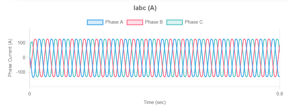
fig.2 : Stator Phase Current (A) vs Time (sec)
2) Armature Phase Currents (A) vs Time (sec)
This graph shows the armature currents for the three phases of the PMSM. The currents are sinusoidal and 120° out of phase, indicating balanced operation. Such waveforms confirm proper synchronization and torque production under standard motor conditions.
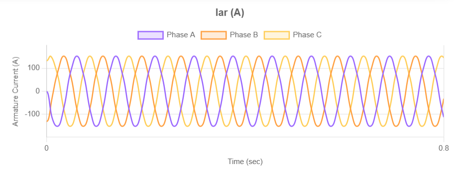
fig.3 : Armature Phase Current (A) vs Time (sec)
3) Rotor Speed Response (RPM) vs Time (sec)
This graph represents the rotor speed of the PMSM over time. A clear step change in speed is observed, demonstrating how the motor responds to sudden reference speed changes. The system shows stable operation with quick adaptation, reflecting effective speed control.
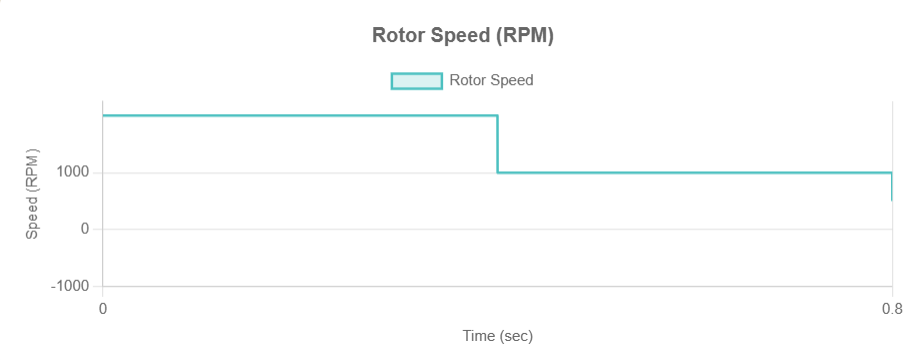
fig.4 : Rotor Speed (RPM) vs Time (sec)
4) Rotor Electrical Angle (rad) vs Time (sec)
This graph shows the rotor electrical angle varying linearly with time and wrapping after 2 𝜋 2π radians. The sawtooth pattern reflects continuous rotation and periodic resetting in the electrical frame. It indicates steady motor motion and proper angular tracking.
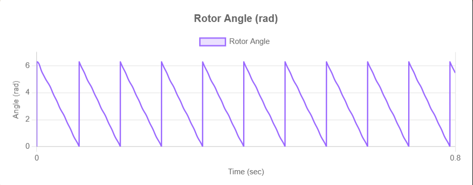
fig.5 : Rotor Angle (rad) vs Time (sec)
5) Electromagnetic Torque Response (N-m) vs Time (sec)
This graph depicts the electromagnetic torque generated by the PMSM. Initial oscillations settle quickly, indicating transient response stabilization. The steady ripple around a constant average value confirms effective torque control and dynamic performance.

fig.6 : Electromagnetic Torque (N-m) vs Time (sec)
6) DC Link Voltage (V) vs Time (sec)
This graph shows the DC link voltage supplied to the inverter driving the PMSM. The voltage remains constant at around 300 V, ensuring stable inverter operation. A steady Vdc is critical for consistent motor performance and reliable control.

fig.7 : DC Link Voltage (V) vs Time (sec)
Advantages of PMSM Motor Drive
• High efficiency: No rotor copper losses.
• Better dynamic response: Fast acceleration and deceleration.
• Compact size: Higher power density than induction motors.
• Excellent speed regulation: Constant speed under varying load.
• Low maintenance: No brushes or commutators.
• Quiet operation: Less noise and vibration.
Disadvantages of PMSM Motor Drive
• High initial cost: Permanent magnets are expensive.
• Demagnetization risk: Under high temperature or fault conditions.
• Complex control: Requires sophisticated controllers and feedback sensors.
• Sensitive to overload: Prolonged overcurrent can damage magnets.
Applications of PMSM Drive Performance Analysis
- Electric Vehicles (EVs): Accurate torque-speed mapping for drive cycle simulation.
- Industrial Automation: Efficient motor selection for conveyor systems.
- Robotics: Precise control required for smooth motion.
- Aerospace: PMSM used in actuators where dynamic response is critical.
Conclusion
This experiment helps students and engineers understand the behavior of PMSM under different operational scenarios, analyze the effectiveness of FOC, and optimize performance parameters. The virtual lab approach ensures safety, repeatability, and cost-effective training.