
Theory
Introduction
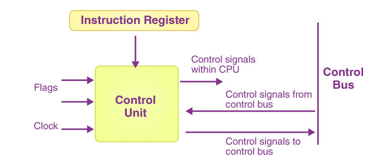
In any processor, the control unit plays a central role in directing the flow of data and operations. It determines which operations the Arithmetic Logic Unit (ALU), memory, and registers perform during each instruction cycle. The control unit's design is crucial because it manages the execution of the instruction set by producing various control signals.
In this experiment, we will design a control unit for a simple instruction set. The goal is to ensure that each instruction is executed correctly by generating the correct control signals at each stage of the instruction cycle.
Aim:
The aim of this experiment is to design a control unit for a simple instruction set using logic gates. The control unit will generate appropriate control signals for different components, such as RAM, registers, ALU, and various logic gates during the execution of instructions.
Objective:
1 - To design a control unit using basic logic gates (AND, OR, NOT, XOR) to manage the operations of components like RAM, registers, and ALU.
2 - To generate control signals for the read and write operations in RAM, ALU operations (e.g., addition, subtraction), and control signals for input and output operations.
3 - To implement a simple instruction set architecture (ISA) that triggers specific control signals during the execution of each instruction.
4 - To demonstrate how the control unit interacts with the processor components (RAM, registers, ALU) to perform data manipulation and processing based on the instruction set.
RAM (Random Access Memory):
• Definition: RAM is a type of volatile memory used to store data and machine code that a processor can access quickly. In the context of your control unit design, RAM stores instructions that need to be executed.
• Role in Experiment: In a simple control unit design, RAM holds the instructions that are fetched and executed by the control unit. The control unit reads instructions from RAM and decodes them to produce control signals that drive the execution of these instructions.
Registers:
• Definition: A register is a small, fast storage location within the CPU used to hold data temporarily during execution. Registers are crucial for storing operands, results of computations, and addresses during the instruction cycle.
• Role in Experiment: In your control unit design, registers can hold intermediate data for instruction execution. For example, in an instruction like ADD R1, R2, the registers R1 and R2 would hold the operands, and the result would be stored back in a register.
ALU (Arithmetic Logic Unit):
• Definition: The ALU performs all arithmetic and logical operations, such as addition, subtraction, AND, OR, etc. It is a crucial component in executing computational instructions.
• Role in Experiment: In the context of the control unit, the ALU is controlled by the signals generated by the control unit based on the instruction. If the instruction requires an arithmetic operation, the ALU will perform it based on the operands provided by the registers.
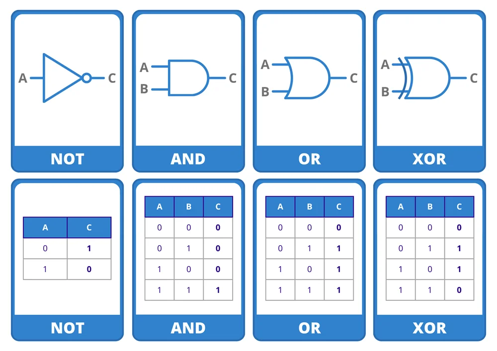
Logic Gates:
• Definition: Logic gates are basic building blocks used to perform logical operations. Common types of logic gates include AND, OR, NOT, XOR, NAND, and NOR. Logic gates are used to implement decision-making processes in a control unit.
• Role in Experiment: In a control unit, logic gates are used to generate control signals based on the instruction bits. For example, depending on the opcode (operation code) of an instruction, a specific logic gate configuration will produce the necessary control signals to route data to the correct register or ALU.
Control Signals:
1- Read and Write Control Signals:
• Manage data flow between RAM, registers, and the ALU.
2- Carry Control:
• Determines whether the carry flag is set or reset after arithmetic operations in the ALU.
3- ALU Operation Signals:
• Control the type of operation performed by the ALU, such as addition or subtraction.
3- Input/Output Signals:
• Control the input and output operations for data transfer.
Instruction Set Architecture (ISA):
The ISA defines the operations that the control unit will manage, including:
• Arithmetic operations (e.g., ADD, SUB)
• Logical operations (e.g., AND, OR, XOR)
• Memory operations (e.g., LOAD, STORE)
• Control operations (e.g., HALT, JUMP)
Logic Design:
The control unit uses combinational logic circuits (constructed from logic gates) to generate signals that control the timing of memory reads/writes, ALU operations, and data movement. Each instruction in the ISA corresponds to a unique set of control signals that direct the components on what to do.
Observations:
• The control unit generates a set of signals that control the ALU, RAM, and registers, ensuring that the right operation is performed at each stage of instruction execution.
• The ALU performs operations like addition or subtraction, and the correct values are read from and written to the RAM and registers as needed.
• The simulation demonstrates the sequential processing of instructions, where each instruction set the proper control signals for the hardware components.
Conclusion: In this experiment, we designed and simulated a control unit for a simple instruction set using basic logic gates. The control unit effectively generated control signals that managed the operations of RAM, registers, the ALU, and input/output components. This experiment demonstrated the essential role of the control unit in coordinating the operation of a processor and ensuring the correct execution of instructions. Through this simulation, we also gained a deeper understanding of how control signals are generated and how they interact with the system components to execute the desired operations.