
Theory
Introduction
This experiment focuses on utilizing the ALU and registers as the primary components to simulate a simplified microprocessor. The ALU performs essential arithmetic (addition, subtraction) and logical (AND, OR, XOR) operations, while registers store the operands and intermediate results. By integrating these components, the simulation demonstrates the interaction between the ALU and registers, mimicking a microprocessor's data processing capabilities.
Microprocessor Overview
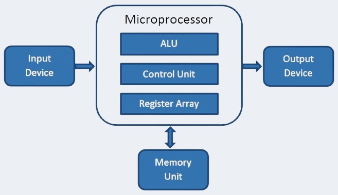
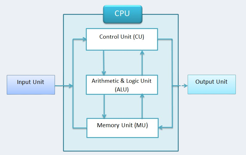
A microprocessor performs operations by following instructions stored in memory. Each instruction generally includes:
• Operation Code (Opcode): Specifies the operation (e.g., ADD, AND).
• Operands: Specifies the data to be processed (e.g., values in registers).
In this experiment, only the ALU and registers are used, meaning the memory and control units are abstracted or predefined.
Arithmetic Logic Unit (ALU):
• The ALU is a combinational circuit responsible for performing arithmetic and logical operations.
• Examples of operations:
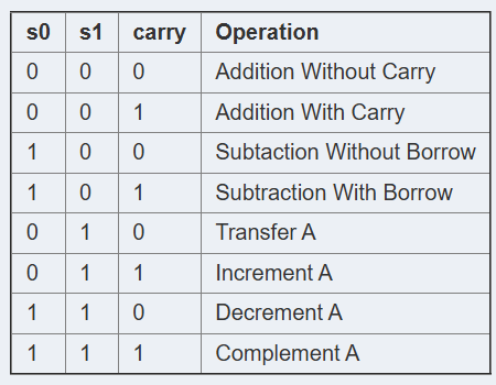
Arithmetic: Addition, subtraction, increment, decrement, etc.
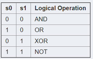
Logical: AND, OR, XOR, NOT, etc.
Registers:
• Registers are small, fast memory units located within the processor.
• They temporarily hold data (operands) that the ALU processes.
• Typically, two registers (e.g., R1 and R2) are used for this simulation:
• R1: Stores the first operand or result.
• R2: Stores the second operand.
Working of Register:
In the experiment, the register serves as a crucial storage element within the microprocessor simulation. It temporarily holds data or operands, which are then processed by the Arithmetic Logic Unit (ALU). The input data is first loaded into the register, which acts as an intermediary storage before the ALU performs its arithmetic or logical operations. After the ALU processes the data, the result is stored back in the register, where it can be accessed for further computation or sent as output. The register ensures smooth data flow between the input, ALU, and output, enabling efficient processing in the microprocessor system.
ALU and Register Integration
The ALU and registers interact through the data path:
Input Stage:
• The ALU takes input from two registers, typically R1 and R2.
• Each operation is triggered by an opcode (e.g., 0001 for addition).
• Processing Stage:
• The ALU performs the operation specified by the opcode using the data in the registers.
• For arithmetic operations, the ALU performs bit-wise calculations based on addition or subtraction logic.
• For logical operations, Boolean algebra is applied.
• Output Stage:
The result is sent back to a register (e.g., R1) for storage.

Execution Process:
• Initialization:
Assign initial values to the registers.
Example: R1 = 10, R2 = 20.
• Instruction Dispatch:
-> Select the operation (e.g., ADD, AND) using an opcode.
-> Opcodes are decoded to signal the ALU.
• ALU Operation:
The ALU performs the operation based on the opcode.
Example:
Opcode 0001 → ADD: R1 + R2.
Opcode 0010 → AND: R1 & R2.
• Result Observation:
The output of the ALU is stored in a register and observed.
Key Observations:
1- Data Dependency:
• The ALU operations are dependent on the values in registers R1 and R2.
• Incorrect loading of data leads to incorrect results.
2- Operation Speed:
• The ALU executes operations in a single clock cycle, but loading and storing data might introduce delays.
3- No Memory Access:
• Since only registers are used, the simulation does not involve fetching data from external memory, simplifying the operation.
Applications:
• Understanding the data flow in a processor.
• Demonstrating how ALU processes instructions.
• Observing the effect of instruction set architecture (ISA) on processor behavior.
Conclusion: This experiment demonstrates the integration of an ALU with registers to simulate microprocessor behavior. By executing arithmetic and logical instructions, you can observe how the ALU manipulates data and produces results, providing insights into the fundamental workings of a microprocessor's execution unit.