
Theory
Introduction
In digital electronics, the behavior of microcontrollers can be simulated using fundamental logic components such as flip-flops and logic gates. These components serve as the building blocks for designing complex digital systems, and by combining them effectively, we can replicate the operation of a microcontroller to understand its functionality. The experiment focuses on using AND gates, flip-flops, clocks, and inputs/outputs to simulate the basic behavior of a microcontroller. Flip-flops, which are bistable circuits, store binary data and are essential in building sequential logic circuits. They act as memory elements, holding a state based on the clock signal they receive. By controlling the clock and input signals, flip-flops can change states, allowing us to mimic the operation of registers and other memory elements found in microcontrollers. Logic gates, particularly the AND gate, are used to create combinational logic that governs the flow of data and decision-making within the system. These gates are responsible for processing input signals and controlling the output based on the defined logical conditions. The clock signal plays a crucial role in this simulation by synchronizing the flip-flops and other sequential elements. The clock dictates when data changes or updates, ensuring that operations occur at the correct moments. The input signals provide the necessary conditions or data to the system, while the output signals represent the result of the system’s operations.
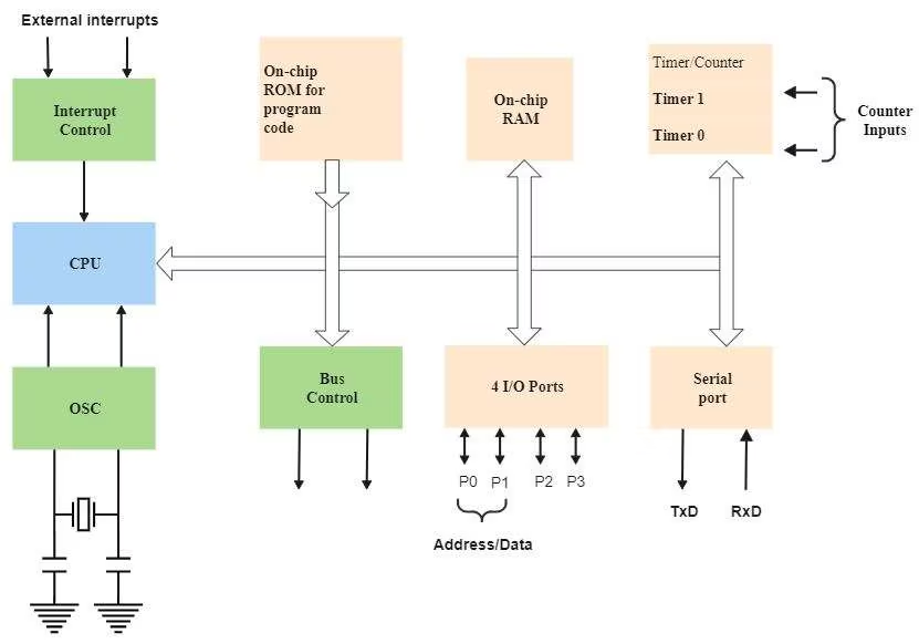
Figure-1: Microcontroller Block diagram
Microcontroller
A microcontroller is a compact integrated circuit designed to
perform specific tasks in embedded systems. It combines a processor
(CPU), memory (RAM and ROM), and input/output peripherals into a
single chip. Microcontrollers are commonly used in systems that
require low power consumption, real-time control, and automation,
such as robotics, automotive systems, and consumer electronics.
At its core, a microcontroller performs basic instructions like
addition, subtraction, and data manipulation using its Arithmetic
Logic Unit (ALU). These instructions manipulate data stored in
registers, with the results often affecting status flags (such as
zero, carry, overflow) that provide feedback on the operation's
outcome.
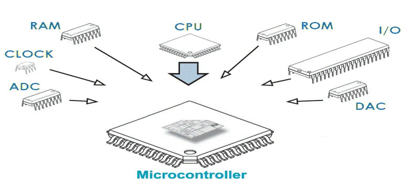
Figure-2: Microcontroller
Flip-Flops in Digital Circuits
Flip-flops are the fundamental building blocks of registers and
memory elements in digital systems. A flip-flop is a bistable
multivibrator, meaning it has two stable states, which it can switch
between based on its input signals. Flip-flops are used to store
binary information, making them essential in registers, counters,
and other memory elements in microcontrollers.
• D Flip-Flop: A D flip-flop captures the input
data on the rising or falling edge of a clock signal, making it
ideal for building registers and synchronizing data storage.
• JK Flip-Flop: A more complex flip-flop used for
more flexible operations, including toggling and state control.

Figure-3: D-Flip Flop
Logic Gates
Logic gates perform basic logical operations on binary inputs and
produce a binary output. These gates (AND, OR, NOT, XOR, etc.) are
the fundamental elements that allow microcontrollers to process data
and make decisions.
• AND Gate: Outputs 1 only if both inputs are 1.
• OR Gate: Outputs 1 if at least one input is 1.
• NOT Gate: Outputs the opposite of the input
value.
• XOR Gate: Outputs 1 if only one input is 1, but
not both.

Figure-4: Logic Gates
Registers
Registers are small, fast storage elements in a microcontroller that
hold data temporarily during processing. Registers are typically
used to store intermediate values during calculations, address
pointers, and status flags. The most important registers in a
microcontroller include:
Types of Registers
• Accumulator (AC): A special register used to store intermediate results of arithmetic and logical operations performed by the ALU. It reduces the need for frequent memory access.• Instruction Register (IR): Holds the currently executing instruction fetched from memory. The control unit decodes the instruction stored in this register.
• Program Counter (PC): Keeps track of the address of the next instruction to be executed. It is automatically updated after fetching an instruction.
• Memory Address Register (MAR): Stores the address of a memory location that is being accessed for either reading data from or writing data to memory.
• Memory Data Register (MDR) Holds the actual data being transferred to or from memory. It acts as a buffer between the processor and memory.
Arithmetic Logic Unit (ALU)
The Arithmetic Logic Unit (ALU) is a core component of a
microcontroller or microprocessor responsible for performing all
arithmetic and logical operations. It takes input data, processes it
based on control signals, and outputs the result to registers.
Typical operations in an ALU include:
• Arithmetic operations: such as addition,
subtraction, multiplication, and division.
• Logical operations: such as AND, OR, NOT, and
XOR.
• Bitwise operations: including shifts and
rotations.
Control signals determine which operation the ALU performs. Status
flags, like the zero, carry, and overflow flags, indicate the
result's characteristics (e.g., if the result is zero or if there’s
a carry-out). These flags are essential for decision-making within
the microcontroller, enabling it to perform more complex
computations and control tasks based on the ALU’s output.

Figure-5: Arithmetic Logic Unit