
Theory
Three Voltmeter Method
The 3-voltmeter method is used to measure the inductance, resistance, quality factor, and power absorbed of a choke coil.
A choke coil can be represented as a pure inductance in series with an equivalent resistance that accounts for core losses and inherent resistance.
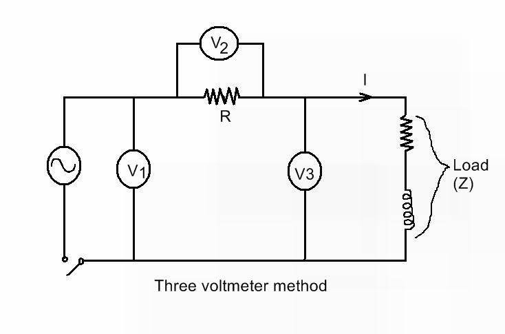
Three Voltmeter method for measurement of power:
The three voltmeter is used in an inductive circuit to
measure the value of the power factor. As seen on Figure
above , one voltmeter is used to measure the voltage of the
circuit (Ui), the second one measures the voltage on the
non-inductive resistance (UR) that is connected in the
series with the load branch and the third voltmeter is used
to measure the voltage of the load (Ut).
This concept is illustrated in following figures.
Three voltmeter method vector diagram
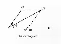
V1, V2 and V3 are the three voltmeters and R is a non-inductive resistance connected in series with the load as shown in figure.
From the phasor diagram, we have:
V12 = V22+ V32 + 2 V2V3CosΦ
but,
V2 = I* R
V12 = V22+ V32 + 2 (I*R) V3CosΦ
V12 = V22+ V32 + 2 R (V3ICosΦ)
V12 = V22+ V32 + 2 PR
Since the power in Inductive Circuit,
P = V I3CosΦ
or Power,
⇒P = ( V12- V22- V32 ) \2R
Power factor of circuit is given by,
CosΦ = ( V12- V22- V32 ) \ 2 V2V3