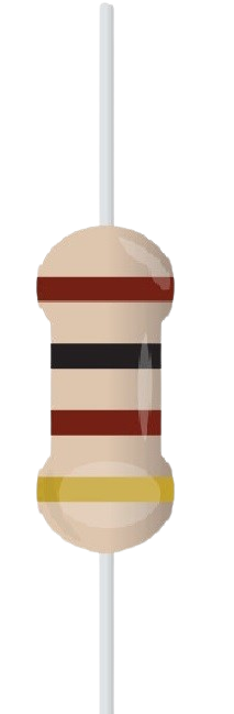
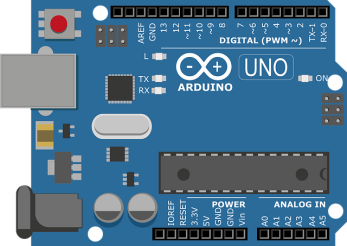
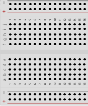
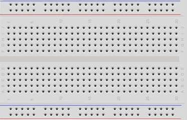
Detection of the light using photo resistor
INSTRUCTIONS
Step-1(Info.)
1.)
Source
2.)
Target
Note:
Make Connections First, Then move to the code Compilation
Step-2 (Connections)
1.)Drag and drop BreadBoard,Arduino and all other Components first.
2.)Connect
Pin 1
with
Pin 2
of breadboard..
3.)Connect
source Pin
of LED with
Pin 3
of Breadboard.. And
target Pin
of LED with
Pin 2
of Breadboard
4.)Connect
Pin 4
of breadboard with
Pin 11
of Arduino.
5.)Connect
Pin 5
of breadboard with
Pin 7
of breadboard.
6.)Connect
Gnd Pin
of Arduino with
Pin 6
of Breadboard & Connect
Pin (5V)
of arduino with
Pin 8
of Breadboard.
7.)Connect
Pin 7
of breadboard with
Pin (A1)
of arduino.
8.)Click on
"CHECK"
button to check the connections.
Step-3 (Code Compilation)
1.) Set the ldrPin of ledPin as
"INPUT"
2.) Set the ledPin to
"OUTPUT"
.
3.) Click on
"COMPILE"
button to run and check the code.
4.) Rightclick on
"LDR"
& set the input value between 1 to 5.
Components
LDR
LED
Resister 1
Arduino
BreadBoard
3
4
7
8
1
2
5
6
Bread Board
LED
Name :
Resister1
Value (1-5)
LDR
Name :
Resister1
Value
1 k ohm Register
Arduino UNO
Code Compiler
int
ldrPin = A1;
int
ledPin = 11;
int
sensorValue = 0;
void
setup() {
pinMode
(ldrPin,
);
pinMode
(ledPin,
);
Serial.
begin(9600);
}
void
loop() {
sensorValue =
analogRead
(ldrPin);
delay
(sensorValue );
int
brightness =map(sensorValue, 0, 1023, 0, 255);
Serial.
println
((brightness));
analogWrite
(ledPin, brightness);
delay
(100);
}
CHECK
RESET
COMPILE
PRINT
© 2024 | Virtual Labs, IIT Roorkee