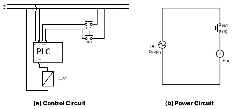
Components
Relay
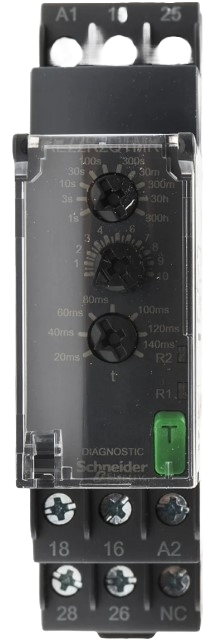
Relay
 rotate.png)
No (R)
Push to ON
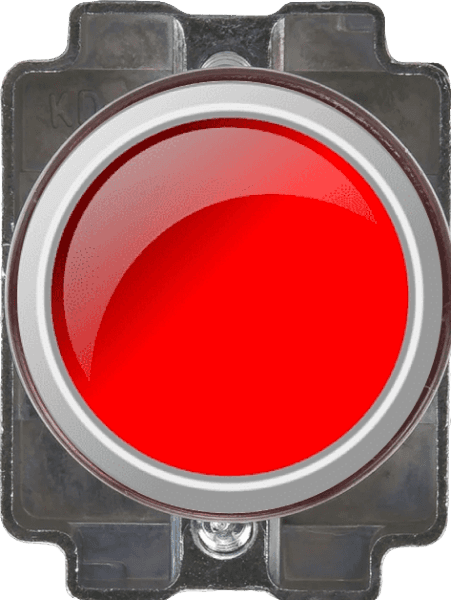
Push to ON
PLC
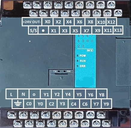
PLC
DC Load
DC Motor
Supply
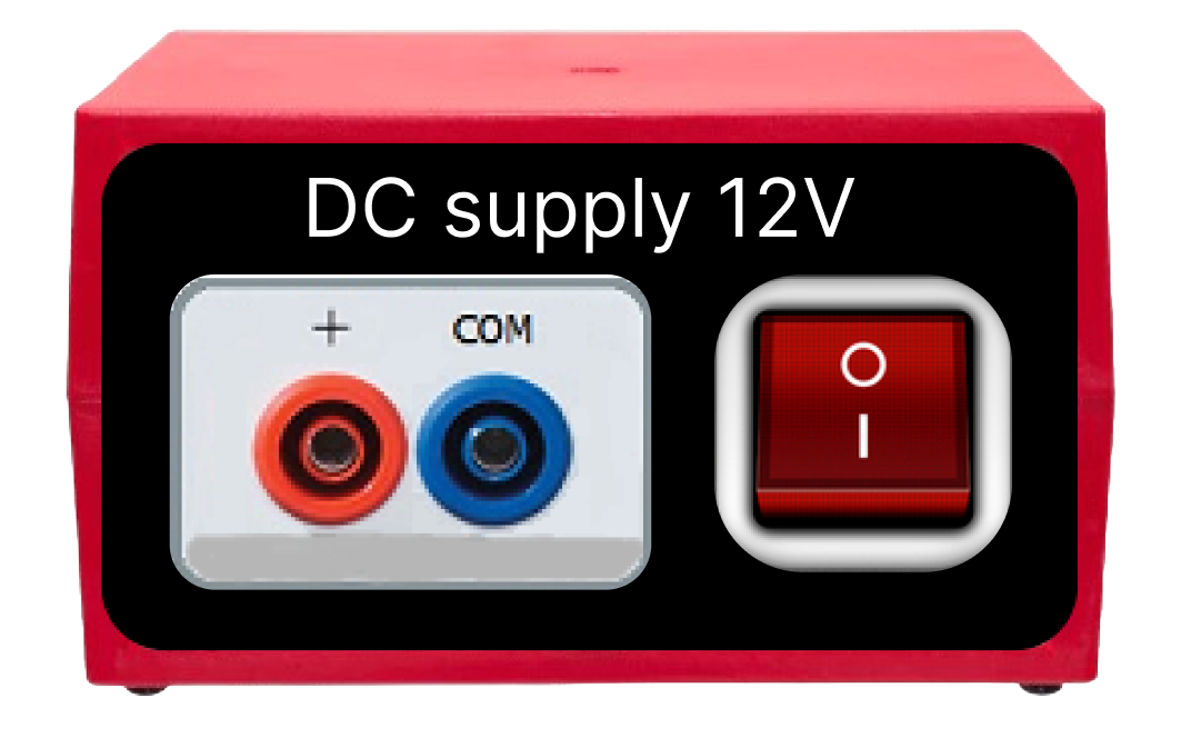
DC Supply
Control circuit
PLC
4C/O Relay 12V DC
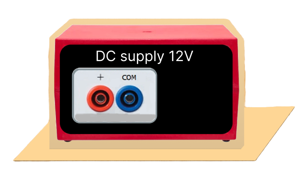

DC supply 12V
X0
X1
Power circuit