INSTRUCTIONS
Instructions
STEP 1 : Make the connections as per the instructions given below
:
V1 --> SA, V2 --> SB, SA --> D1, SB --> D2,
ⵊ1 --> C1, ⵊ2 --> C2, ⵊ3 --> C3,
C4 --> M1, C5 --> M2, C6 --> M3, M --> R,
T1 --> T4, T2 --> T5, T3 --> T6,
P1 --> P4, P2 --> P5, P3 --> P6
STEP 2 : Click on "CHECK" button for checking the connections.
Note: Click on a label to remove the connection.
STEP 3 : Click on "START" button to perform the experiment.
STEP 4 : Click on "GRAPH" button to open the graph.
STEP 5 : Click on "PRINT" button to print the simulation.
STEP 6 : Click on "RESET" button to reset the experiment.

DC DC Converter
SA
SB
D1
D2
ⵊ1
ⵊ2
ⵊ3
P3
P2
P1
M1
M2
M3
M

S1
S2
S3
S4
S5
S6

T4
T5
T6
P6
P5
P4
R

C1
C2
C3
C4
C5
C6
T1
T2
T3
a
b
c
a'
b'
c'
N
S
BLDC Motor
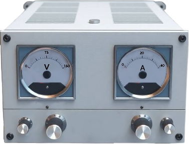
V1
V2
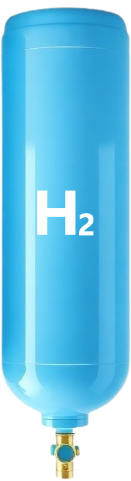
Hydrogen Fuel Cell
Anode
Cathode