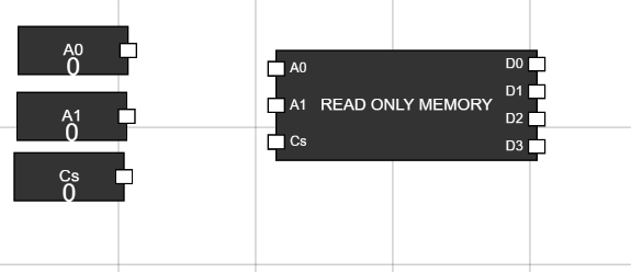
Step 1: Take Read Only Memory and Inputs
- Navigate to the Components section and select the Read Only Memory (ROM) component.
- Add three input components and rename them as A0, A1, and Cs. Figure 1: ROM and Inputs in Workspace
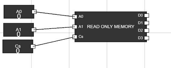
Step 2: Connect Inputs to Read Only Memory
- Connect the inputs A0, A1, and Cs to their corresponding A0, A1, and Cs pins on the Read Only Memory. Figure 2: Inputs Connected to ROM
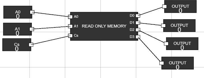
Step 3: Add Outputs and Connect Them
- Add four output components and connect them to the D0, D1, D2, and D3 pins of the Read Only Memory. Figure 3: Outputs Connected to ROM
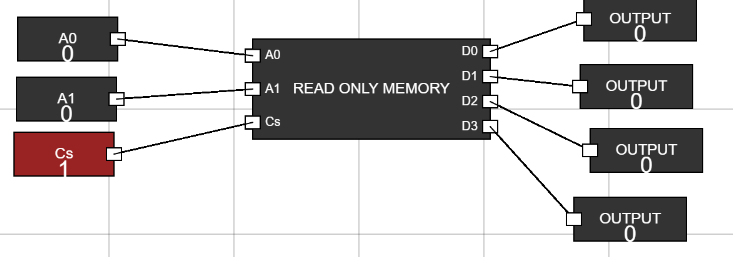
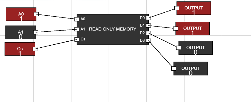
Step 4: Set Cs to 1
- Set the Cs input to 1 to enable the Read Only Memory. Figure 4: Cs Set to 1
Step 5: Change Address and Observe Data
- Use the inputs A0 and A1 to change the address.
- Observe the output data at D3, D2, D1, and D0 based on the following truth table: