Step 1: Set Up Components:
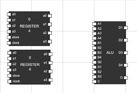
- Navigate to the Components section and ALU, 2 Registers to the workspace. Figure 1: Components in
Worspace
Step 2: Take 17 inputs to provide inputs to Registers and ALU:
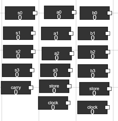
- Rename the input by Hover over the input and clicking CTRL+A. This will open a alert box to input new name for any input.
- Using this, rename inputs as a0, a1, a2 and a3 to connect to data input of first register.
- Similarly rename inputs as b0, b1, b2 and b3 to connect to data inputs of second register.
- Rename two inputs to store and two inputs to clock to connect them to store and clock inputs of registers.
- Rename other 4 inputs to s0, s1, s2 and s3 to connect to select inputs for ALU.
- Rename the last input to carry to connect to carry input of ALU. Figure 2: Add Inputs
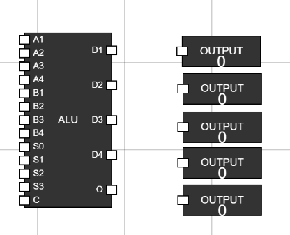
Step 3: Take 5 outputs to the workspace to display ALU output along with overflow bit: Figure 3: Outputs on workspace
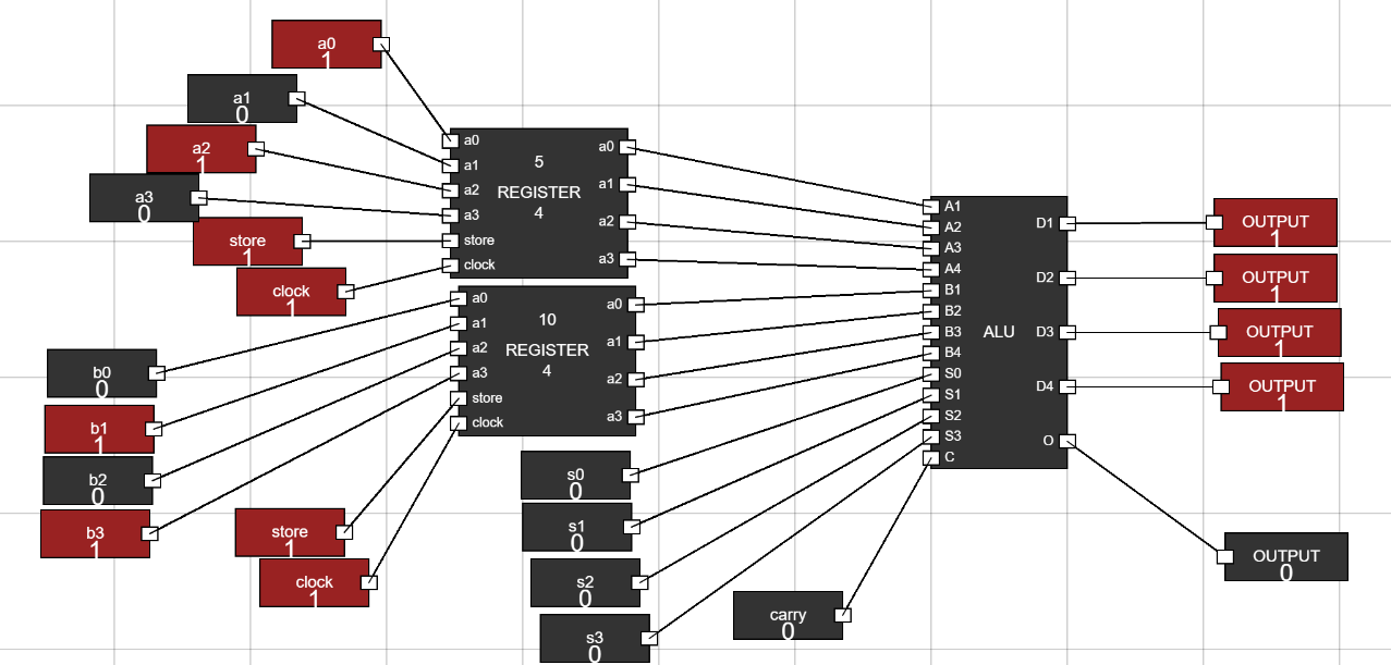
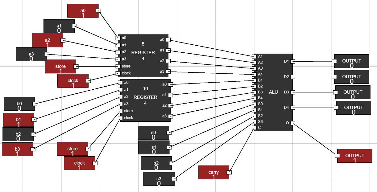
Step 4: Connect the inputs :
- Connect data bits to registers as shown in figure.
- Connect store and clock inputs to registers as well.
- Connect select inputs and carry input to ALU.
- Connect the outputs of two registers to the data input of ALU.
- Last, Connect the output of ALU to the 5 outputs we have moved to workspace. Figure 4: Connections
Step 5: How to simulate :
- Make the store and clock inputs of Registers to 1(high) to enter data into registers.
- Change the data input bits to feed data into registers.
- Now, s2 and s3 bit of ALU tells, what kind of operation ALU will perform.
s2
s3
Type of Operation
0
0
Arithmetic Operation
0
1
Logical Operation
1
0
Right Shift
1
1
Left Shift
- s0 and s1 tells which operation will be performed of a certain type.
- There are 8 arithmetic operations that can be performed using s0, s1 and carry input.
s0
s1
carry
Operation
0
0
0
Addition Without Carry
0
0
1
Addition With Carry
1
0
0
Subtaction Without Borrow
1
0
1
Subtraction With Borrow
0
1
0
Transfer A
0
1
1
Increment A
1
1
0
Decrement A
1
1
1
Complement A
- There are 4 logical operations that can be performed using s0 and s1 input.
s0
s1
Logical Operation
0
0
AND
1
0
OR
0
1
XOR
1
1
NOT
- Now, by changing the select inputs and carry input of ALU, observe the changes. Figure 5: Arithmetic addition without carry. Figure 6: Arithmetic addition with carry.