Procedure
- Step 1: Add a D Flip-Flop and Two Inputs
- Navigate to the Components section and add a D Flip-Flop and two Input components to the workspace.
- Rename the inputs as IE (Input Enable) and CLK (Clock).

Figure 1: D Flip-Flop and Inputs - Step 2: Connect IE and CLK
- Connect the IE input to the D input of the D Flip-Flop.
- Connect the CLK input to the Clock input of the D Flip-Flop.
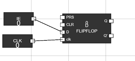
Figure 2: IE and CLK Connected - Step 3: Add an AND Gate and IRQ Input
- Add an AND gate and one Input component to the workspace.
- Rename the Input as IRQ (Interrupt Request).
- Connect the IRQ input to one input of the AND gate.
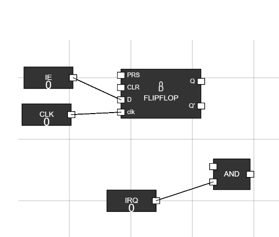
Figure 3: AND Gate and IRQ Connected - Step 4: Use a Junction
- Add a Junction to the workspace.
- Connect the Q output of the D Flip-Flop to the Junction.
- Connect one output of the Junction to a new Output component and the other to the second input of the AND gate.
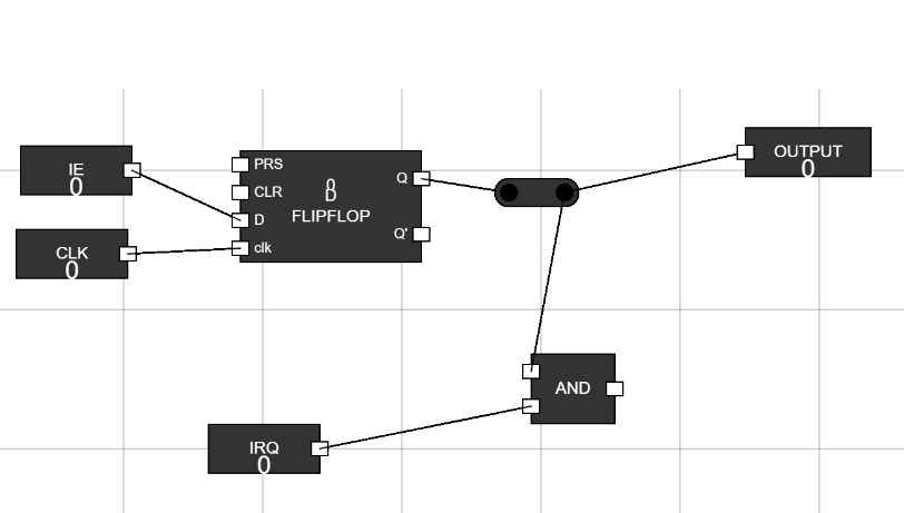
Figure 4: Junction Connections - Step 5: Add a MUX and ISR Input
- Add a MUX (Multiplexer) and an Input component to the workspace.
- Rename the Input as ISR (Interrupt Service Routine).
- Connect the ISR input to one input of the MUX.
- Connect the output of the AND gate to the S0 input of the MUX.
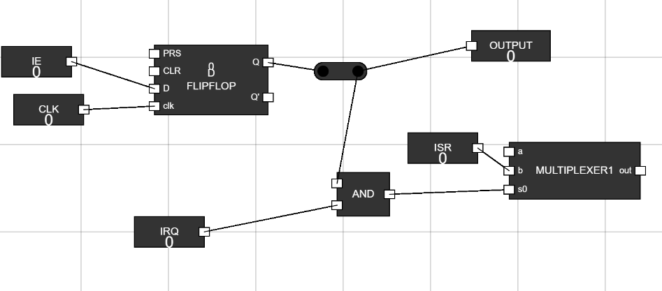
Figure 5: MUX and ISR Connected - Step 6: Add a Flip-Flop
- Add a Flip-Flop to the workspace.
- Connect the output of the MUX to the D input of the Flip-Flop.
- Add an Input component, rename it CLK, and connect it to the Clock input of the Flip-Flop.
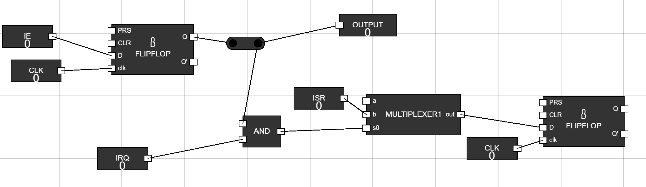
Figure 6: Flip-Flop Connected - Step 7: Add a Junction for Flip-Flop Output
- Use a Junction to connect the Q output of the Flip-Flop.
- Connect one output of the Junction to a new Output component and another to an input of the MUX.
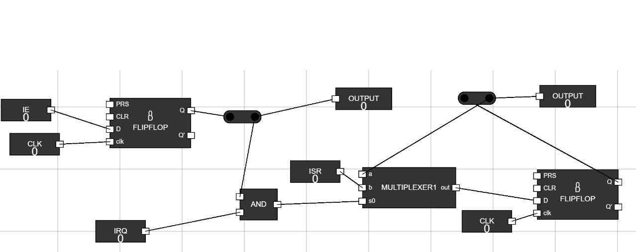
Figure 7: Junction for Flip-Flop Output - Step 8: Provide Inputs and Test
- Set the IRQ and ISR inputs to 1.
- Observe the behavior of the circuit and verify the outputs.
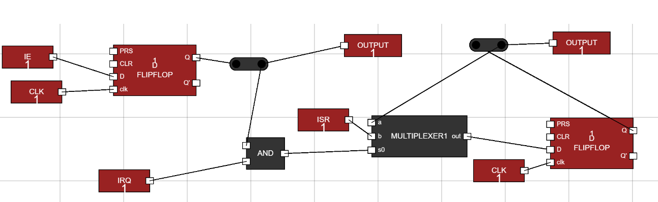
Figure 8: Final Testing